Hi
I have now fitted a new digital clock to the existing aperture on the instrument cluster, however when i went and restored the instrument cluster in to the dash and power it up I am not getting any voltage at the plug socket where the existing digital clock plugged into the instrument cluster PCB via the white 2 pin plug,
So the first question is
1. What is the voltage of the digital clock which was originally fitted??
2. Does any one have a wiring diagram/ current flow diagram for the digital clock.
3. Is an English translastion of the PCB tracks identification available - Where the instrument cluster plugs into the wiring loom the PCB tracks in the socket have labels but they are in German.
This would be a great help to enable me to trace it though from the +ve supply, through some components to the clock white plug and back to -ve
Thanks Dave
Digital Clock Current Flow Diagram
Moderators: User administrators, Moderators
-
DokaDave
- Registered user
- Posts: 18
- Joined: 08 Oct 2013, 05:07
- 80-90 Mem No: 13023
- Location: Doncaster
Digital Clock Current Flow Diagram
1990 DoKa Syncro 1.9AAZ
Imagination is more important than knowledge.
Imagination is more important than knowledge.
-
ZsZ

- Registered user
- Posts: 1584
- Joined: 12 Feb 2009, 16:28
- 80-90 Mem No: 14899
- Location: Budapest, Hungary
- Contact:
Re: Digital Clock Current Flow Diagram
2:
http://www.kpcnsk.com/wp-content/upload ... tpanel.jpg (cannot link as a picture, too wide)
from here: http://www.kpcnsk.com/?p=138
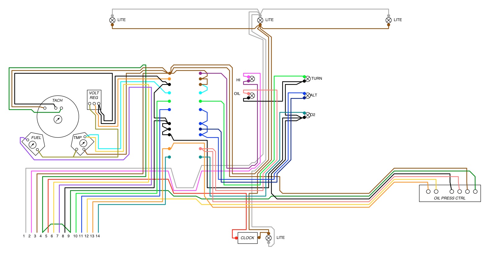
3:
Pin-Nr. Terminal - Cable color
New (from model year 1985)
1 Instrumentlights - grey/blue
2 Full beam - blue/white
3 Earth (term. 31) - brown
4 Free
5 Battery positive (term. 30) - red
6 Coolant temp. - yellow/red
7 Fuel level - purple/black
8 Ignition positive (term. 15) - black
9 Tachometer (term. W) - green
10 Indicator - blue/red
11 Alternator (term. D+) - blue
12 Oil pressure switch 1,4/0,9 bar (D/TD) - yellow
13 Oil pressure switch 0,3 bar - blue/black
14 Glow plug - white/red
Old (up to model year 1984)
1 Free
2 Earth (term. 31) - brown
3 Instrumentlights - grey/blue
4 Full beam - blue/white
5 Earth (term. 31) - brown
6 Coolant temp.- yellow/red
7 Battery positive (term. 30) - red
8 Fuel level - purple/black
9 Ignition positive (term. 15) - black
10 Oil pressure switch 0,3 bar - blue/black
11 Free
12 Glow plug - white/red
13 Alternator (term. D+) - blue
14 Indicator - blue/red
http://www.kpcnsk.com/wp-content/upload ... tpanel.jpg (cannot link as a picture, too wide)
from here: http://www.kpcnsk.com/?p=138
3:
Pin-Nr. Terminal - Cable color
New (from model year 1985)
1 Instrumentlights - grey/blue
2 Full beam - blue/white
3 Earth (term. 31) - brown
4 Free
5 Battery positive (term. 30) - red
6 Coolant temp. - yellow/red
7 Fuel level - purple/black
8 Ignition positive (term. 15) - black
9 Tachometer (term. W) - green
10 Indicator - blue/red
11 Alternator (term. D+) - blue
12 Oil pressure switch 1,4/0,9 bar (D/TD) - yellow
13 Oil pressure switch 0,3 bar - blue/black
14 Glow plug - white/red
Old (up to model year 1984)
1 Free
2 Earth (term. 31) - brown
3 Instrumentlights - grey/blue
4 Full beam - blue/white
5 Earth (term. 31) - brown
6 Coolant temp.- yellow/red
7 Battery positive (term. 30) - red
8 Fuel level - purple/black
9 Ignition positive (term. 15) - black
10 Oil pressure switch 0,3 bar - blue/black
11 Free
12 Glow plug - white/red
13 Alternator (term. D+) - blue
14 Indicator - blue/red
Zoltan
1986 Multivan ex-Caravelle. Van since 2006, running mTDi 1Z since 2008 with Fiat Croma 1.9 TDid pump 2008-2019, custom pump since 2019
5spd custom box 4.57 diff + 0.74 5th
1986 Multivan ex-Caravelle. Van since 2006, running mTDi 1Z since 2008 with Fiat Croma 1.9 TDid pump 2008-2019, custom pump since 2019
5spd custom box 4.57 diff + 0.74 5th
-
DokaDave
- Registered user
- Posts: 18
- Joined: 08 Oct 2013, 05:07
- 80-90 Mem No: 13023
- Location: Doncaster
Re: Digital Clock Current Flow Diagram
Hi
Many many thanks ZsZ for the info it is more than I could ask for.
I will now be able to make some progress.
It very much looks like I have a broken track.
DD
Many many thanks ZsZ for the info it is more than I could ask for.
I will now be able to make some progress.
It very much looks like I have a broken track.
DD
1990 DoKa Syncro 1.9AAZ
Imagination is more important than knowledge.
Imagination is more important than knowledge.
-
garyd

- Registered user
- Posts: 490
- Joined: 20 Sep 2006, 18:36
- 80-90 Mem No: 2934
- Location: Wells, Somerset
Re: Digital Clock Current Flow Diagram
Good luck with sorting out the wiring side.
I would be interested to know what clock you have fitted. Is it an original VW one or sourced from somewhere else? How straightforward was the fitting?
thanks
I would be interested to know what clock you have fitted. Is it an original VW one or sourced from somewhere else? How straightforward was the fitting?
thanks
Garyd
1990 Transporter syncro camper
2 litre AGG 'GTi' engine
1990 Transporter syncro camper
2 litre AGG 'GTi' engine
-
DokaDave
- Registered user
- Posts: 18
- Joined: 08 Oct 2013, 05:07
- 80-90 Mem No: 13023
- Location: Doncaster
Re: Digital Clock Current Flow Diagram
Gary
I will try and document something when i have sorted out the final solution. But at the moment it is ongoing.
It is not an original vw clock The clock is from China of all places, but it came within 2 weeks and works ok.
http://www.ebay.co.uk/itm/330774904780? ... 5060wt_952" onclick="window.open(this.href);return false;
So far i have a few issues with the clock
1. The back light is very bright it needs to be dimmed some how will have to fit a pot to trim the voltage and current or see if the original light dimmer is sufficient.
2. Mounting the clock in the original frame and aperture is difficult to get the hole centres correct which enables it to sit flush and central with the facia.
3. Mounting the set buttons in the original facia.
I will keep you upload some photos to keep you posted.
As suspected I have several broken tracks on the pcb to wiring loom connector so it requires replacing or track repairs which will be difficult to solder and not destroy the surrounding plastic. So i may have to lift the tracks, solder then reglue in position. watch this space.
DD
1990 DoKa Syncro 1.9AAZ
Imagination is more important than knowledge.
Imagination is more important than knowledge.