Headlamp relay updrade/mod

An alchemy of sparks, copper wire and earth

Moderators: User administrators, Moderators

KINGPRAWN
Registered user
Posts: 888
Joined: 29 Jul 2010, 15:38
80-90 Mem No: 9516
Location: penzance cornwall

Headlamp relay updrade/mod

Post by KINGPRAWN »

I have just finished this electrical mod to get full power lights!!
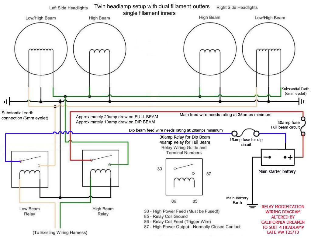
Can anybody confirm which relay tags do what I have ...
#86 as power source
#87 as the low or high beam feed out
#85 as ground
#30 as the trigger from fuse board ( yellow and yellow/black) for the low beams and white for the high beam .i did cut the black/white (high beam) but it has nowhere to plug into?
All works like lasers!!! Except for the R/H (square twin lamp unit) which is dim as dim.. The single high beam same side is perfect!!! So I have 4 out of 6 success ...
Also the relays are permanently warm ( constant live feed not switched as I couldn't find any spare) is this right ??????? :?
in too deep to quit now....

User avatar
AdrianC
Registered user
Posts: 2975
Joined: 29 Dec 2010, 21:57
80-90 Mem No: 9144
Location: Living in Hay whilst the Sun pours down.
Contact:

Re: Headlamp relay updrade/mod

Post by AdrianC »

Image

No, you've got 'em the wrong way round...

What you're doing is having the relay permanently on, hence the warmth, then switching the supply which the relay passes to the bulbs - and still passing full lighting current through the light switch.

87/30 is the switched pair, 85/86 is the switching pair. When current flows between 85/86, over the relay coil, that pulls the relay's contact towards it, breaking the circuit to 87a (normally closed) and closing it to 87 (normally open), so "switching off" between 30 and 87a and "switching on" between 30 and 87.

So...
30 - to fused +12v feed (battery)
87 - to lights
85 - to earth
86 - to original lighting wire, switched +12v.
(85/86 can be the other way round)

You're best off taking the +12v for pin 30 straight from the battery, with a fuse as near as possible to the battery, since that'll give you the cleanest, fullest, fattest supply possible. Also well worth replacing the earths from the bulbs, to ensure that the power you're supplying can "get back" easily.

To do the main beams, you'll need a second relay.
Last edited by AdrianC on 23 Jan 2013, 15:45, edited 1 time in total.
A year and a half living in a Westy hightop... http://www.WhereverTheRoadGoes.com" onclick="window.open(this.href);return false;

KINGPRAWN
Registered user
Posts: 888
Joined: 29 Jul 2010, 15:38
80-90 Mem No: 9516
Location: penzance cornwall

Re: Headlamp relay updrade/mod

Post by KINGPRAWN »

Thanks Mr A ...
in too deep to quit now....

MidLifeCrisis
Registered user
Posts: 566
Joined: 20 Nov 2011, 19:07
80-90 Mem No: 10519
Location: Bagshot, Surrey

Re: Headlamp relay updrade/mod

Post by MidLifeCrisis »

AdrianC wrote:
"that'll give you the cleanest, fullest, fattest supply possible."
Classic!!! I'm using this as my description of a good 12V supply from now on !!! :ok
1987 Westfalia Van, Petrol 2.0 AGG

California Dreamin
Registered user
Posts: 2673
Joined: 03 Apr 2007, 12:54
80-90 Mem No: 8386
Location: Nottingham

Re: Headlamp relay updrade/mod

Post by California Dreamin »

Just follow my diagram matey..personally I wouldn't use a 5 pin relays (just confuse things), you only need standard 4 pins.
The maximum current flowing is around 20 amps but I like to have plenty of headroom so used a 40amp relay for the full beam and a 30amp for the dip.

See:


Image

Note* TWO seperate live feeds directly from the battery, this ensures dip and full beam are kept apart for redundancy (if one circuit fails the other remains working).

Martin
1989 California 2.1MV

KINGPRAWN
Registered user
Posts: 888
Joined: 29 Jul 2010, 15:38
80-90 Mem No: 9516
Location: penzance cornwall

Re: Headlamp relay updrade/mod

Post by KINGPRAWN »

California Dreamin wrote:Just follow my diagram matey..personally I wouldn't use a 5 pin relays (just confuse things), you only need standard 4 pins.
The maximum current flowing is around 20 amps but I like to have plenty of headroom so used a 40amp relay for the full beam and a 30amp for the dip.

See:


Image

Note* TWO seperate live feeds directly from the battery, this ensures dip and full beam are kept apart for redundancy (if one circuit fails the other remains working).

Martin
Thanks... I have been following Mr AXEMANS setup , think I have it Sussed now ..... Thanks for your advice
in too deep to quit now....

California Dreamin
Registered user
Posts: 2673
Joined: 03 Apr 2007, 12:54
80-90 Mem No: 8386
Location: Nottingham

Re: Headlamp relay updrade/mod

Post by California Dreamin »

Ahhh! is that the relay only mod? the one which uses the original wiring to the lamps?

Martin
1989 California 2.1MV

KINGPRAWN
Registered user
Posts: 888
Joined: 29 Jul 2010, 15:38
80-90 Mem No: 9516
Location: penzance cornwall

Re: Headlamp relay updrade/mod

Post by KINGPRAWN »

California Dreamin wrote:Ahhh! is that the relay only mod? the one which uses the original wiring to the lamps?

Martin
No everything replaced!!
in too deep to quit now....

KINGPRAWN
Registered user
Posts: 888
Joined: 29 Jul 2010, 15:38
80-90 Mem No: 9516
Location: penzance cornwall

Re: Headlamp relay updrade/mod

Post by KINGPRAWN »

Sorted... Relay corrections sorted... And one poor earth.... AMAZING!!! Thanks all :ok
in too deep to quit now....

User avatar
axeman
Registered user
Posts: 1246
Joined: 07 Feb 2009, 19:50
80-90 Mem No: 6410
Location: Smeeth kent country side

Re: Headlamp relay updrade/mod

Post by axeman »

California Dreamin wrote:Just follow my diagram matey..personally I wouldn't use a 5 pin relays (just confuse things), you only need standard 4 pins.
The maximum current flowing is around 20 amps but I like to have plenty of headroom so used a 40amp relay for the full beam and a 30amp for the dip.

See:


Image

Note* TWO seperate live feeds directly from the battery, this ensures dip and full beam are kept apart for redundancy (if one circuit fails the other remains working).

Martin

your drawing makes complete sense and has a nice logical approach to the the upgrade. the only thing that i did and advised andy to do was to to use a separate relay for each of the dip beam circuits, this in my mind allows you to use the fused outputs from the fuse board as a trigger for the relay and if there is a problem with either circuit it remains independent from the other one,
i then used one relay for the mine beam and spliced the out put wire as per your drawing, and did the same for the front fog lights taking the trigger from the factory fog light switch , ie first click dose the front fog, second click front and back fogs are on.

glad that your sorted now and the road should be much brighter from now on.

neil
Back in the game with an uncut 2wd panel van

California Dreamin
Registered user
Posts: 2673
Joined: 03 Apr 2007, 12:54
80-90 Mem No: 8386
Location: Nottingham

Re: Headlamp relay updrade/mod

Post by California Dreamin »

So does this mean you have four seperate fused feeds all the way back to the starter battery? this is the only way that all four circuits (left dip/right dip/full beam and fog lights) can be truely independant and give 'redundancy' as you describe it.
Fitting two relays, to keep the dip beams seperate is pointless if those relays share the same feed (if the fuse blows on that feed then both dip beams fail)

Martin
1989 California 2.1MV

User avatar
Titus A Duxass
Registered user
Posts: 5777
Joined: 24 Nov 2007, 08:22
80-90 Mem No: 4475
Location: Cologne

Re: Headlamp relay updrade/mod

Post by Titus A Duxass »

I built some redundancy into mine.
I have 2 feeds, 1 for left dip & right high, vicky verky for the other feed.
probably OTT butwork has a large parts bin.
VW T3 GTi Camper 2,0l

User avatar
axeman
Registered user
Posts: 1246
Joined: 07 Feb 2009, 19:50
80-90 Mem No: 6410
Location: Smeeth kent country side

Re: Headlamp relay updrade/mod

Post by axeman »

California Dreamin wrote:So does this mean you have four seperate fused feeds all the way back to the starter battery? this is the only way that all four circuits (left dip/right dip/full beam and fog lights) can be truely independant and give 'redundancy' as you describe it.
Fitting two relays, to keep the dip beams seperate is pointless if those relays share the same feed (if the fuse blows on that feed then both dip beams fail)

Martin

yep for the diped beams they have there own separate feeds the main and fog feed was taken from the spare switch live feeds on the rear of the fuse baard.

neil
Back in the game with an uncut 2wd panel van

User avatar
ScienceBoy
Registered user
Posts: 275
Joined: 14 Sep 2012, 18:56
80-90 Mem No: 11736
Location: New Forest

Re: Headlamp relay updrade/mod

Post by ScienceBoy »

axeman wrote: and did the same for the front fog lights taking the trigger from the factory fog light switch , ie first click dose the front fog, second click front and back fogs are on.

Neil?
Have got anything to describe the front fog fitting and connections. I've just been figuring out the switch when I caught your post almost by accident. Cheers
Last edited by ScienceBoy on 21 Feb 2013, 22:42, edited 1 time in total.
1988 Hightop
1.9 DG Petrol

User avatar
axeman
Registered user
Posts: 1246
Joined: 07 Feb 2009, 19:50
80-90 Mem No: 6410
Location: Smeeth kent country side

Re: Headlamp relay updrade/mod

Post by axeman »

from memory the wire it's a white wire with a yellow strip that is used as switched live feed from the fog light switch for the front fogs

neil
Back in the game with an uncut 2wd panel van

Post Reply