pre-1984 fusebox wiring
Moderators: User administrators, Moderators
pre-1984 fusebox wiring
Does a simple diagram exist on what colour wire goes in what position on the old type fuse box? I've got a spaghetti mess and no idea what connects where 
1980 Joker Westfalia CU
-
Robsey

- Registered user
- Posts: 1496
- Joined: 19 May 2012, 20:45
- 80-90 Mem No: 11137
- Location: East Manchester
Re: pre-1984 fusebox wiring
UPDATE - There is now!! - Just read on.
Diagrams are on page 2 of this thread.
Continuing the original post.
Here is a link to a thread with the fusebox listing.
Otherwise, you need to find an early wiring ladder diagram.
viewtopic.php?t=171627
Failing that, is there anything particular that you are looking for - something that is not working.
Wire colours are ususlly standard between early torpedo fuse boxes and the later CE1 blade fuse boxes.
If nobody has a list to hand, then I will see what I can create at the weekend.
If you can wait that long.
Thankfully not many wires on a 1980 van.
I suspect the green-coloured early air-cooled Haynes may be able to help.
(The blue water-cooled version is too vague due to various changes in later vans) and does not cover the early fuse box wiring diagrams.
Last edited by Robsey on 31 Jul 2022, 14:19, edited 2 times in total.
1983 Tin Top with a poorly DF and 4 speed DT box.
1987 Electrics and a DJ engine.
Maybe one day I might get it finished
1987 Electrics and a DJ engine.
Maybe one day I might get it finished
Re: pre-1984 fusebox wiring
Hi,
Thanks for the reply. We bought our camper as a project with everything in boxes and the bus completely striped. I've never worked on a T3, so it's been an adventure!
I found that fuse list, but it's not what I'm looking for. I am looking for a list of the back of the fuse panel. What colour wire attaches in what position. I have the Bentley but find those schematics completely unreadable :/
I do not want to burn anything when I connect power for the first time
E D I T: like this picture but with mention of the wire colours
1980 Joker Westfalia CU
-
Robsey
- Registered user
- Posts: 1496
- Joined: 19 May 2012, 20:45
- 80-90 Mem No: 11137
- Location: East Manchester
Re: pre-1984 fusebox wiring
Okay - I have just gone through the early fusebox pin out.
Very confusing, but hopefully this will make sense.
Fuse 1 (8amp)
Left Side and Tail Lights.
IN - Grey from Fuse 2 IN (1.0mm)
Out - Grey/Black -Side Light Left (0.5mm)
Out - Grey/Black - Tail Light Left (0.5mm)
Fuse 2 (8amp)
Right Side and Tail Lights.
IN - Grey from Fuse 1 IN (1.0mm)
IN - Grey - Light Switch pin 58 (1.0mm)
Out - Grey/Red - Side Light Right (0.5mm)
Out - Grey/Red - Tail Light Right (0.5mm) then at tail light connector...Grey/Green - Number Plate Lights (0.5mm)
Fuse 3 (8amp)
Low Beam Left
IN - Copper Strip Link from Fuse 4
Out - Yellow - Headlamp Low Beam Left (1.5mm)
Fuse 4 (8amp)
Low Beam Right
IN - Copper Strip Link from Fuse 3
IN - Yellow/Black - From Beam Flasher Stalk Switch pin 56b (2.5mm)
Out - Yellow/Black - Headlamp Low Beam Right (1.5mm)
Fuse 5 (8amp)
High Beam Left
IN - Copper Strip Link from Fuse 6
Out - White - Headlamp Left High Beam (1.5mm)
Out - Blue/White - Instrument High Beam Light (0.5mm)
Fuse 6 (8amp)
High Beam Right
IN - Copper Strip Link from Fuse 5
IN - White - From Beam Flasher Stalk Switch pin 56a (2.5mm)
Out - White/Black - Headlamp Right High Beam (1.5mm)
Fuse 7 (16amp)
Radiator Fan
IN - Red from Fuse 8 IN (4.0mm)
Out - Red/Black - Rad Fan Switch (2.5mm)
Out - Red - Rad Fan Relay (2.5mm)
Fuse 8 (8amp)
Brake Lights, Cigaretter Lighter and Interior Lights.
IN - Copper Strip Link from Fuse 9
IN - Red from Fuse 7 IN (4.0mm)
IN - Red from Fuse 10 IN (4.0mm)
Out - Red - Cigarette Lighter (1.5mm)
Out - Red/Yellow - Brake Light Switches (1.0mm)
Out - Red - Interior Lights (0.5mm)
Fuse 9 (16amps)
Battery Live Input
IN - Copper Strip Link from Fuse 8
IN - Red/Yellow - Instrument Panel "30" (1.5mm)
IN - Red - Ignition Switch Pin 30 (4.0mm)
IN - Red/Yellow - Headlamp High/Low Beam Stalk pin 30 (1.5mm)
IN - BATTERY PLUS TERMINAL (6.0mm)
Out - Red/White - Hazard Switch & Radio (1.5mm)
Fuse 10 (16amp)
Relief / X Contact Power
IN - Black/Yellow - X Contact Relay pin 87 (4.0mm)
IN - Black/Yellow - To Fuse 13 IN
Out - Link then Black/Red to Blower Motor. (1.0mm)
Out - Black/Grey - Wiper Switch Pin 53a (1.0mm)
Out - Black/Grey - Wiper Relay Pin 15 (1.0mm)
Fuse 11 (8amp)
Ignition Live / Ignition
IN - Copper Strip Link from Fuse 12
IN - Linked then Black - Ignition Coil (1.5mm)
Out - Black/Blue - Hazard Switch Pin 15 (1.5mm)
Fuse 12 (8amp)
Horn, Reverse Lights, Instruments Ignition Live.
IN - Copper Strip Link from Fuse 11
IN - Black - Ignition Switch Pin 15 (1.5mm)
IN - Black - Coolant Level Module pin 15. (1.0mm)
Out - Black/Blue - Reverse Lights (1.5mm)
Out - Black/Yellow - Horn (1.0mm)
Fuse 13 (8amp)
Rear Window Demister.
IN - Black/Yellow -from IN side of Fuse 10 and X Contact Relay Pin 87
Out - Black/White - Rear Window Demister Switch
I hope this helps.
Last edited by Robsey on 31 Jul 2022, 08:31, edited 3 times in total.
1983 Tin Top with a poorly DF and 4 speed DT box.
1987 Electrics and a DJ engine.
Maybe one day I might get it finished
1987 Electrics and a DJ engine.
Maybe one day I might get it finished
-
Robsey
- Registered user
- Posts: 1496
- Joined: 19 May 2012, 20:45
- 80-90 Mem No: 11137
- Location: East Manchester
Re: pre-1984 fusebox wiring
And the Relays...
X Contact Relay
Type 18 / 24 / 100
Pin 30 - Red - Unfused side of Fuse 8 (4.0mm)
Pin 87 - Black/Yellow - Unfused side of Fuse 10 (4.0mm)
Pin 86 - Black/ Yellow from Ignition Switch pin X (1.0mm)
Pin 85 - Brown to Chassis / Earth Crowns (0.5mm)
------------------------------------
Hazard Light / Flasher Relay
Type 21 (standard) / 22 (with trailer).
Pin 31 - Brown to Chassis / Earth Crowns (0.5mm)
Pin 49 - White - Hazard Switch Pin 49
Pin 49a - Blue/Red - Instrument Pin T14/14
(Indicator tell tale LED). (0.5mm)
Pin 49a - Black/Green/White - Hazard Switch Pin 49a
-----------------------
Intermittent Wiper Relay
Type 19 / 99 (adjustable delay).
Pin J - Brown/Black - Wiper Switch Pin J
Pin T - Green/Red - Wiper Switch Pin T
And to Window Washer Pump.
Pin 15 - Black/Grey - Fuse 10
Pin 15 - Black/Grey - Wiper Motor pin 53a
Pin 31 - Brown - Chassis / Earth Crown
Pin 53e - Green/White - Wiper Motor pin 53e
Pin 53m - Green - Wiper Switch Pin 53e
Last edited by Robsey on 25 Mar 2023, 09:57, edited 4 times in total.
1983 Tin Top with a poorly DF and 4 speed DT box.
1987 Electrics and a DJ engine.
Maybe one day I might get it finished
1987 Electrics and a DJ engine.
Maybe one day I might get it finished
Re: pre-1984 fusebox wiring
Thank you so much! This is exactly what I was looking for!
1980 Joker Westfalia CU
-
Robsey
- Registered user
- Posts: 1496
- Joined: 19 May 2012, 20:45
- 80-90 Mem No: 11137
- Location: East Manchester
Re: pre-1984 fusebox wiring
I don't know how confident you are with the electrics, or what your overall plans are, but
Now is also a good time to add in any upgrades or updates.
You could consider adding one of the headlamp upgrade relay looms - there are plenty of kits available.
Others add extras like a hard-start relay kit, if you are worried that the original wiring would struggle to crank the engine.
Or - you could keep it simple, and keep the van all original. By far the 'easiest' route to go down.
1983 Tin Top with a poorly DF and 4 speed DT box.
1987 Electrics and a DJ engine.
Maybe one day I might get it finished
1987 Electrics and a DJ engine.
Maybe one day I might get it finished
Re: pre-1984 fusebox wiring
It's a project we bought in boxes and it was missing the wiring loom. I've made one stock original one out of 2 donors. Removed all the dodgy added wiring. When it's all original and working I'll consider upgrades. In a safe manner. It's my second total car rebuild/ restoratiin. Thank God for the internet 
And thanks for the above! You saved the day!
And thanks for the above! You saved the day!
1980 Joker Westfalia CU
-
Rosie n' Jim
- Registered user
- Posts: 238
- Joined: 06 Sep 2020, 06:40
- 80-90 Mem No: 0
Re: pre-1984 fusebox wiring
Try a search on Ebay for 'VW T25 wiring diagram'. Someone has done laminated old style diagrams. Different variants are available, makes things so much easier!
1982 Holdsworth poptop. 2L CU Aircooled.
1982 Danbury tintop Caravelle. 2L CU Aircooled.
1982 Danbury tintop Caravelle. 2L CU Aircooled.
-
Robsey
- Registered user
- Posts: 1496
- Joined: 19 May 2012, 20:45
- 80-90 Mem No: 11137
- Location: East Manchester
Re: pre-1984 fusebox wiring
I found a picture of my old fusebox as it came out of the van...
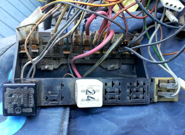
And photos from today, showing wiring to / from the relays.
(Partially stripped many years ago to use parts to convert my van to the later CE1 fusebox ).


Note the very fat black/yellow from the fuse output to the relay.
And the fat red in the first picture.
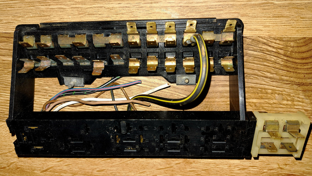
And also that both relay earths are linked by a thin brown wire.
My relay 24 was my X Contact relay. Many vans will have relays number 18 or 100 instead.
Remember that the coolant level module (numbered 42 or 43) is mounted on its own little relay plate on the A pillar near to the earth crowns.
(UPDATE - Ignore that, you have an Aircooled - even easier)
And photos from today, showing wiring to / from the relays.
(Partially stripped many years ago to use parts to convert my van to the later CE1 fusebox ).
Note the very fat black/yellow from the fuse output to the relay.
And the fat red in the first picture.
And also that both relay earths are linked by a thin brown wire.
My relay 24 was my X Contact relay. Many vans will have relays number 18 or 100 instead.
Remember that the coolant level module (numbered 42 or 43) is mounted on its own little relay plate on the A pillar near to the earth crowns.
(UPDATE - Ignore that, you have an Aircooled - even easier)
1983 Tin Top with a poorly DF and 4 speed DT box.
1987 Electrics and a DJ engine.
Maybe one day I might get it finished
1987 Electrics and a DJ engine.
Maybe one day I might get it finished
-
Robsey
- Registered user
- Posts: 1496
- Joined: 19 May 2012, 20:45
- 80-90 Mem No: 11137
- Location: East Manchester
Re: pre-1984 fusebox wiring
If like me, you do not have a rear window demister.
The wires on the extension for fuse 13 are for dimmed illumination instead
Fuse 13 - 8 amps
IN - Grey / Blue - Dimmed illumination feed from Light Switch pin 58b (0.5mm)
Out - Grey / Blue - Dimmed illumination to instrument panel bulbs. (0.5mm)
To be honest there are as many variations as there are clouds in the sky.
Just Found -
Fuse 14 - 8 amps
Rear Warm Air Blower
IN - White / Yellow - X Contact Feed from Fuse 10 IN (2.5mm)
Out - Black - T1 Connector (1.0mm)
Out - Black / Yellow - V47 Rear Warm Air Blower Switch (E100) (1.5mm)
Last edited by Robsey on 30 Jul 2022, 07:47, edited 1 time in total.
1983 Tin Top with a poorly DF and 4 speed DT box.
1987 Electrics and a DJ engine.
Maybe one day I might get it finished
1987 Electrics and a DJ engine.
Maybe one day I might get it finished
Re: pre-1984 fusebox wiring
Rosie n' Jim wrote: ↑24 Jul 2022, 05:08 Try a search on Ebay for 'VW T25 wiring diagram'. Someone has done laminated old style diagrams. Different variants are available, makes things so much easier!
Thanks! Those look a thousand times better then the Haynes
1980 Joker Westfalia CU
Re: pre-1984 fusebox wiring
Thanks, I indeed do not have rear demist. Your list helps me a lot!! Best info i've gottenRobsey wrote: ↑24 Jul 2022, 23:17 If like me, you do not have a rear window demister.
The wires on the extension for fuse 13 are for dimmed illumination instead
Fuse 13 - 8 amps
IN - Grey / Blue - Dimmed illumination feed from Light Switch pin 58b
Out - Grey / Blue - Dimmed illumination to instrument panel bulbs.
To be honest there are as many variations as there are clouds in the sky.
1980 Joker Westfalia CU
-
Robsey
- Registered user
- Posts: 1496
- Joined: 19 May 2012, 20:45
- 80-90 Mem No: 11137
- Location: East Manchester
Re: pre-1984 fusebox wiring
Glad to help.
Just post up if you need any more info.

Just post up if you need any more info.
1983 Tin Top with a poorly DF and 4 speed DT box.
1987 Electrics and a DJ engine.
Maybe one day I might get it finished
1987 Electrics and a DJ engine.
Maybe one day I might get it finished
-
Robsey
- Registered user
- Posts: 1496
- Joined: 19 May 2012, 20:45
- 80-90 Mem No: 11137
- Location: East Manchester
Re: pre-1984 fusebox wiring
UPDATE -
Wire sizes added and
Fuse 14 - Rear Warm Air Blower added.
In all fairness, you could link whatever you wish via the creamy-white 2-fuse piece,
---------------------------------------------
As per another thread - Radio Connection.
There are two potential take off points.
The red battery live may be from fuse 8 or 9, which are linked via a copper strap,
I looked at Fuse 3, and it appears to be for the later CE1 blade-fuse fusebox.
Last edited by Robsey on 31 Jul 2022, 11:00, edited 1 time in total.
1983 Tin Top with a poorly DF and 4 speed DT box.
1987 Electrics and a DJ engine.
Maybe one day I might get it finished
1987 Electrics and a DJ engine.
Maybe one day I might get it finished