I had a good look through my notes.
The pins numbers and wire colours are.
ALL VW ISO Pins Layout.
[ 2 ][ 4 ][ 6 ][ 8 ]
[ 1 [] 3 ][ 5 ][ 7 ]
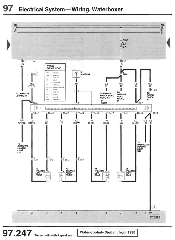
T25 Listing. On (early) mono radios, where only a single dash speaker was used.
Pin 4 - Red - 12 volt live feed.
Pin 6 - Grey / Blue - illumination wire.
Pin 7 - Red - 12 volt live feed
Pin 8 - Brown - Ground Feed.
It shows -
blue / white - dash spesker audio +
Brown or brown / black - dash speaker audio -
On later Alpha / Beta / Gamma stereo radios
This is how I would wire up the radio.
Note the ignition live feed to pin 4, and the permanent live feed to the security code memory on pin 5
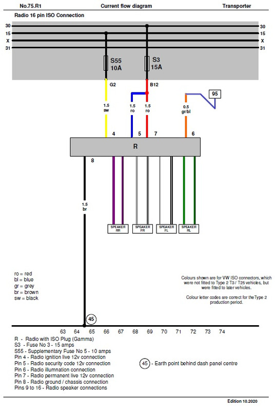
The wire colours for the speakers are "standard" aftermarket colours, as the colour scheme changes on various models and years
The wire "colours" are those reported to be for very early VW ISO wiring.
The two letter codes that stand for the German nane of the colour, would be the T25 version.
Also ignore the fuse number 55.
Because I chose G2 or G5 for ignition controlled live, it is protected by fuse 18.
1983 Tin Top with a poorly DF and 4 speed DT box.
1987 Electrics and a DJ engine.
Maybe one day I might get it finished