Tacho options for a petrol dash?

An alchemy of sparks, copper wire and earth

Moderators: User administrators, Moderators

User avatar
CJH
Registered user
Posts: 3018
Joined: 15 Jul 2013, 06:51
80-90 Mem No: 12576
Location: Nottingham

Re: Tacho options for a petrol dash?

Post by CJH »

bigbadbob76 wrote:hmmmm.... not easy. I'm no programmer but I think you have to do it with interupts.

Yes, it would be nice for the main code loop to do all the maths and the display updates, and for the device to wait for an interrupt to signal that a pulse has started, instead of having to watch the analogue input the whole time. But as far as I can tell, interrupts only work on the digital input pins.

But I think an alternative could be to have a routine that runs for an undisturbed (I was going to say 'uninterrupted') period, say 100ms, to sample the analogue input pin, then returns to the main code with an RPM value. This could then be used to update the display, and when that and any other loop activities are complete the RPM routine would be called again. 100ms would give me plenty of time get an accurate RPM value, and even if it only updated once per second due to slow LCD updates, that would probably be enough to make a reasonable tacho display. Something to work on.


bigbadbob76 wrote:Here's the scope plots anyway-

5v/division, x10 probe, so 375V pk-pk.
no wonder it tingles. :lol:
Image
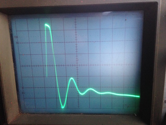
Thank you. What kind of resistor is needed to deal with that?
"I'm a man of means, by no means....King of the Road!"

1983 Viking Xplorer, 2.1DJ

User avatar
bigbadbob76
Registered user
Posts: 1733
Joined: 07 Nov 2016, 14:41
80-90 Mem No: 15707
Location: Isle of Skye

Re: Tacho options for a petrol dash?

Post by bigbadbob76 »

375v - say 5v for the zener= 370v.
370v/say 20mA (current limit through the zener)= 18.5K ohm.
You do the power maths. :wink:
put the zener between your arduino input pin and ground, and the resistor in series with the signal.
'86 1.9 DG, 4 spd, tintop, camper conversion.
Split case club member.

User avatar
CJH
Registered user
Posts: 3018
Joined: 15 Jul 2013, 06:51
80-90 Mem No: 12576
Location: Nottingham

Re: Tacho options for a petrol dash?

Post by CJH »

Thank you. Just to be sure - do you mean like this?

Image

I'm puzzled about the zener now - this is how I understand it should be oriented to achieve a voltage input to the Arduino that will not exceed 5.6V, but it seems to be in a different place/orientation to the one in the tacho circuit that I copied. How does it work in that tacho circuit? And in the Arduino circuit, should I perhaps have two of them, anode-to-anode, to ensure the voltage stays between +5.6V and -5.6V, because the negative spike in your scope photo looks quite big too (~50V)?

Image
"I'm a man of means, by no means....King of the Road!"

1983 Viking Xplorer, 2.1DJ

User avatar
bigbadbob76
Registered user
Posts: 1733
Joined: 07 Nov 2016, 14:41
80-90 Mem No: 15707
Location: Isle of Skye

Re: Tacho options for a petrol dash?

Post by bigbadbob76 »

Top picture is right for the arduino. :ok
It clamps the input to the arduino to no greater than the zener voltage. so you want a zener voltage less than 5V to be safe.
The rest of the volts are dropped across the resistor.

Yes you can use two back to back but make sure you use a zener that is 0.7v less than 5V as the forward biased diode will add to the zener voltage.
To do it really nicely, use an optoisolator instead of the zener.
Drive the led of the optoisolator from the tacho signal via the 18K resistor.
This will keep the high voltages off your sensitive arduino.


The SAK takes up to 20V input, the zener in that circuit is dropping say 5.6V from the voltage that's left after the 33k/3k3 potential divider has divided it by 11.
so for example...
375V input / 11= 34V
34V- 5.6V= 28V

hmmmm..... that zener is probably not 5.6V, it's not marked so whoever drew that ciruit just drew it as a diode.
Last edited by bigbadbob76 on 10 Aug 2018, 13:40, edited 1 time in total.
'86 1.9 DG, 4 spd, tintop, camper conversion.
Split case club member.

User avatar
CJH
Registered user
Posts: 3018
Joined: 15 Jul 2013, 06:51
80-90 Mem No: 12576
Location: Nottingham

Re: Tacho options for a petrol dash?

Post by CJH »

Thank you. Supplementary questions:

1) Any idea why I seem to be seeing ~0.25V on pin 2 of the SAK215?
2) Would anode-to-anode, or cathode-to-cathode, zeners be a good idea in the Arduino circuit?
"I'm a man of means, by no means....King of the Road!"

1983 Viking Xplorer, 2.1DJ

User avatar
bigbadbob76
Registered user
Posts: 1733
Joined: 07 Nov 2016, 14:41
80-90 Mem No: 15707
Location: Isle of Skye

Re: Tacho options for a petrol dash?

Post by bigbadbob76 »

edited above to include optoisolator.
back to back or front to front makes no difference to sheep.... errr.... sorry..
'86 1.9 DG, 4 spd, tintop, camper conversion.
Split case club member.

User avatar
CJH
Registered user
Posts: 3018
Joined: 15 Jul 2013, 06:51
80-90 Mem No: 12576
Location: Nottingham

Re: Tacho options for a petrol dash?

Post by CJH »

bigbadbob76 wrote:edited above to include optoisolator.

Thank you. You're doing a fine job of introducing me to new components one by one.
"I'm a man of means, by no means....King of the Road!"

1983 Viking Xplorer, 2.1DJ

User avatar
bigbadbob76
Registered user
Posts: 1733
Joined: 07 Nov 2016, 14:41
80-90 Mem No: 15707
Location: Isle of Skye

Re: Tacho options for a petrol dash?

Post by bigbadbob76 »

CJH wrote:1) Any idea why I seem to be seeing ~0.25V on pin 2 of the SAK215?

With what input? is this in the van? and what measuring instrument?
A multimeter will try and show you an average voltage. if the duty cycle of the tacho input pulses is low (see my scope plot above) then your meter will show a very low reading.
Scope is the tool for looking at pulses. :wink:
'86 1.9 DG, 4 spd, tintop, camper conversion.
Split case club member.

User avatar
CJH
Registered user
Posts: 3018
Joined: 15 Jul 2013, 06:51
80-90 Mem No: 12576
Location: Nottingham

Re: Tacho options for a petrol dash?

Post by CJH »

bigbadbob76 wrote:
CJH wrote:1) Any idea why I seem to be seeing ~0.25V on pin 2 of the SAK215?

With what input? is this in the van? and what measuring instrument?
A multimeter will try and show you an average voltage. if the duty cycle of the tacho input pulses is low (see my scope plot above) then your meter will show a very low reading.
Scope is the tool for looking at pulses. :wink:

Coil pulse inputs, measured in the van using an Arduino nano connected to pin2 and gnd. In this plot, the y-axis scale goes from 0-1023 to represent 0-5V, so a value of ~50 is ~0.25V. It's quite possible that I did something wrong, so I'm planning to have another go over the weekend.

Image
"I'm a man of means, by no means....King of the Road!"

1983 Viking Xplorer, 2.1DJ

User avatar
bigbadbob76
Registered user
Posts: 1733
Joined: 07 Nov 2016, 14:41
80-90 Mem No: 15707
Location: Isle of Skye

Re: Tacho options for a petrol dash?

Post by bigbadbob76 »

Looking at my scope plot, theres some noisy crap after the main spike. Maybe you sampled that.
I'm out of my comfort zone with digital sampling.


Sent from my iPhone using Tapatalk
'86 1.9 DG, 4 spd, tintop, camper conversion.
Split case club member.

User avatar
CJH
Registered user
Posts: 3018
Joined: 15 Jul 2013, 06:51
80-90 Mem No: 12576
Location: Nottingham

Re: Tacho options for a petrol dash?

Post by CJH »

bigbadbob76 wrote:Looking at my scope plot, theres some noisy crap after the main spike. Maybe you sampled that.
I'm out of my comfort zone with digital sampling.

I don't think that's it - that plot shows several complete pulse cycles. I'm not going to worry about that until I've repeated the process and checked for blunders.

In the meantime I now have a nice little RPM calculation in its own little routine - I call the routine with a parameter to specify how many samples should be averaged, and while it's in that routine it does nothing else - no screen updating, no printing to the serial port - and it returns after the specified number of samples with an RPM value. In my main loop, if I simply call that routine successively and print the results to the serial port, the results are extremely accurate (testing against my signal generator it matches very closely - so that settles the argument over whether to trust the signal generator or my Draper multimeter).

The problem comes when I attempt to write the RPM value to my LCD screen. Even though the write happens only after the RPM routine has returned with a value, somehow the screen writing affects the results. Makes no sense. In fact, if I replace the screen write with a simple 'delay(100)', after the RPM routine, it STILL affects the RPM calculation. There's something I'm not getting. Maybe it's to do with external interrupts happening while I'm in the RPM routine, but I can't disable them because then the clock timer doesn't work. I think I need to join an Arduino forum and post code there to see if someone can explain what I'm missing.
"I'm a man of means, by no means....King of the Road!"

1983 Viking Xplorer, 2.1DJ

User avatar
bigbadbob76
Registered user
Posts: 1733
Joined: 07 Nov 2016, 14:41
80-90 Mem No: 15707
Location: Isle of Skye

Re: Tacho options for a petrol dash?

Post by bigbadbob76 »

I'll watch from the sidelines. :)
Sorry I can't help any further, i've done some basic (excuse the pun) "read a value, write it to display" arduino programming but nothing like this.
'86 1.9 DG, 4 spd, tintop, camper conversion.
Split case club member.

User avatar
bigherb
Registered user
Posts: 2579
Joined: 27 Mar 2008, 13:50
80-90 Mem No: 5789
Location: West Kent

Re: Tacho options for a petrol dash?

Post by bigherb »

bigbadbob76 wrote:
5v/division, x10 probe, so 375V pk-pk.
no wonder it tingles. :lol:
Image


That is good coil switching.
Yes, the back emf from the coil is high 300+ volts
You need a scope to check ignition problems gives you a nice window into the system.

This is what it means from my handheld scope.

Image
1982 Camper 1970 1500 Beetle Various Skoda's, Ariel Arrow

User avatar
CJH
Registered user
Posts: 3018
Joined: 15 Jul 2013, 06:51
80-90 Mem No: 12576
Location: Nottingham

Re: Tacho options for a petrol dash?

Post by CJH »

The main spike seems to be sufficiently higher than the bounces to allow some sort of threshold to be set in a digital pulse counter/tacho. I need to have another play.

In the meantime, I've got a digital tacho that works with my signal generator, and can now also display to a screen! The secret was to put the pulse detection into a timer interrupt routine, where it seems to be safe from other interrupts. I've set it to fire 1000 times a second, which should ensure it catches every pulse, and times them to sufficient accuracy.

Image

Right - this flywheel isn't going to sleeve itself....
"I'm a man of means, by no means....King of the Road!"

1983 Viking Xplorer, 2.1DJ

User avatar
Cobra88
Registered user
Posts: 909
Joined: 03 Apr 2018, 18:24
80-90 Mem No: 16481
Location: Ipswich

Re: Tacho options for a petrol dash?

Post by Cobra88 »

Well done Chris

I knew you would crack it :ok
____________________________________________
84 CaravelleGL 1.9 DG WBX Bronze Beige Metallic auto

Post Reply