Replacing the dashboard plastic PCB
Moderators: User administrators, Moderators
-
CovKid

- Trader
- Posts: 8413
- Joined: 30 Apr 2006, 13:19
- 80-90 Mem No: 3529
- Location: Ralph - Coventry (Retired)
- Contact:
Re: Replacing the dashboard plastic PCB
Putting it together now. Chris has made this EASY 
Roller paint your camper at home: http://roller.epizy.com/55554/" onclick="window.open(this.href);return false; for MP4 download.
-
CovKid
- Trader
- Posts: 8413
- Joined: 30 Apr 2006, 13:19
- 80-90 Mem No: 3529
- Location: Ralph - Coventry (Retired)
- Contact:
Re: Replacing the dashboard plastic PCB
LED standoff tool is spot on.
Roller paint your camper at home: http://roller.epizy.com/55554/" onclick="window.open(this.href);return false; for MP4 download.

Re: Replacing the dashboard plastic PCB
CovKid wrote:LED standoff tool is spot on.
Glad you like it
I've broadened my horizons. No longer do I see every problem as an opportunity to make a PCB. In my world it's now either an opportunity for a PCB *OR* an opportunity to make something with AutoCAD and my 3D printer.
"I'm a man of means, by no means....King of the Road!"
1983 Viking Xplorer, 2.1DJ
1983 Viking Xplorer, 2.1DJ
-
Sir Brixalot
- Registered user
- Posts: 4571
- Joined: 15 Oct 2010, 21:55
- 80-90 Mem No: 8927
- Location: London
Re: Replacing the dashboard plastic PCB
Sir Brixalot wrote:Is it big enough for rear bumpers!
That would be quite a big PCB.
"I'm a man of means, by no means....King of the Road!"
1983 Viking Xplorer, 2.1DJ
1983 Viking Xplorer, 2.1DJ
-
Sir Brixalot
- Registered user
- Posts: 4571
- Joined: 15 Oct 2010, 21:55
- 80-90 Mem No: 8927
- Location: London
Re: Replacing the dashboard plastic PCB
How's about corner repair pieces for speedo etc.
Honorary "Dave"
Re: Replacing the dashboard plastic PCB
Sir Brixalot wrote:How's about corner repair pieces for speedo etc.
Done those! Just been organising some photos this very evening to post in a new thread.
"I'm a man of means, by no means....King of the Road!"
1983 Viking Xplorer, 2.1DJ
1983 Viking Xplorer, 2.1DJ
-
Sir Brixalot
- Registered user
- Posts: 4571
- Joined: 15 Oct 2010, 21:55
- 80-90 Mem No: 8927
- Location: London
Re: Replacing the dashboard plastic PCB
Brilliant. Been using gaffer tape which slides off if I push trip button. I'll deffo have a set
Honorary "Dave"
-
CovKid
- Trader
- Posts: 8413
- Joined: 30 Apr 2006, 13:19
- 80-90 Mem No: 3529
- Location: Ralph - Coventry (Retired)
- Contact:
Re: Replacing the dashboard plastic PCB
Roughly three hours to assemble although could have done it a lot quicker I suppose. Bit like sitting there doing a jigsaw only more productive 
Tomorrow night will plug it in and see if everything works. Much tidier than veroboard and should a problem occur - much easier to get at and diagnose.
Tomorrow night will plug it in and see if everything works. Much tidier than veroboard and should a problem occur - much easier to get at and diagnose.
Roller paint your camper at home: http://roller.epizy.com/55554/" onclick="window.open(this.href);return false; for MP4 download.
Re: Replacing the dashboard plastic PCB
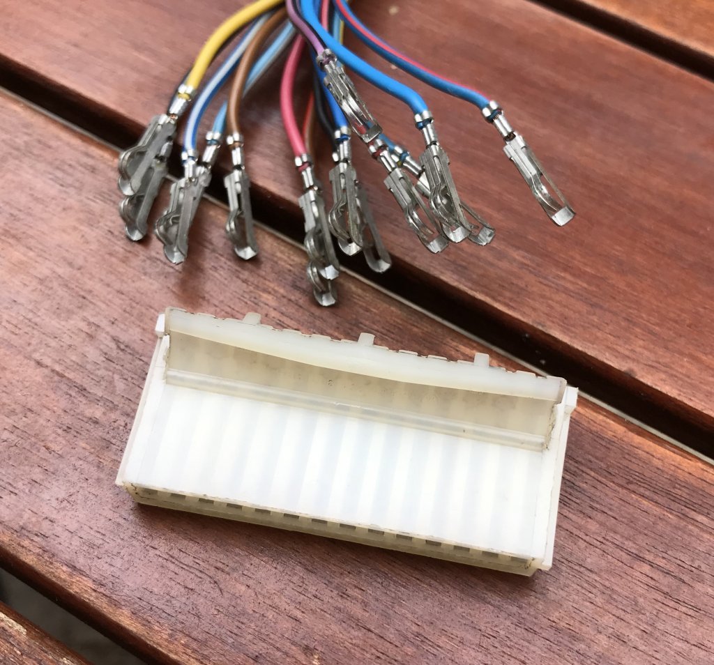
I didn't find a source for new terminals, so I bought a multiplug for a Mk1 Golf. All 14 pins have a nice 25cm length of wire attached. I plan to make up a test harness in case I get into building up my PCB kits. But it will also leave a couple of spare terminals that I can put into the vacant locations (pins 1 and 11) in my own multiplug to feed the spare LEDs.


"I'm a man of means, by no means....King of the Road!"
1983 Viking Xplorer, 2.1DJ
1983 Viking Xplorer, 2.1DJ
Re: Replacing the dashboard plastic PCB
I realised that I actually need to add three terminals, not two: one to feed the glowplugs LED, one for the 6th LED, and one for the tachometer that I'm working on. There are only two unused slots in my multiplug. What to do?
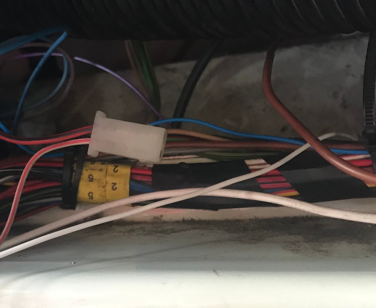
I'd spotted it before but put it to the back of my mind - there's a White/Red wire going into pin 12 of my multiplug. Mine's a pre-85 van, so that makes pin 12 the glowplugs pin, yet my van is a petrol van.
So I traced the White/Red wire through the loom. It ends up at a two pin plug behind the fusebox. The Red/Black wire goes to earth. So evidently unused in my van - must have been a standard fit regardless of engine type.

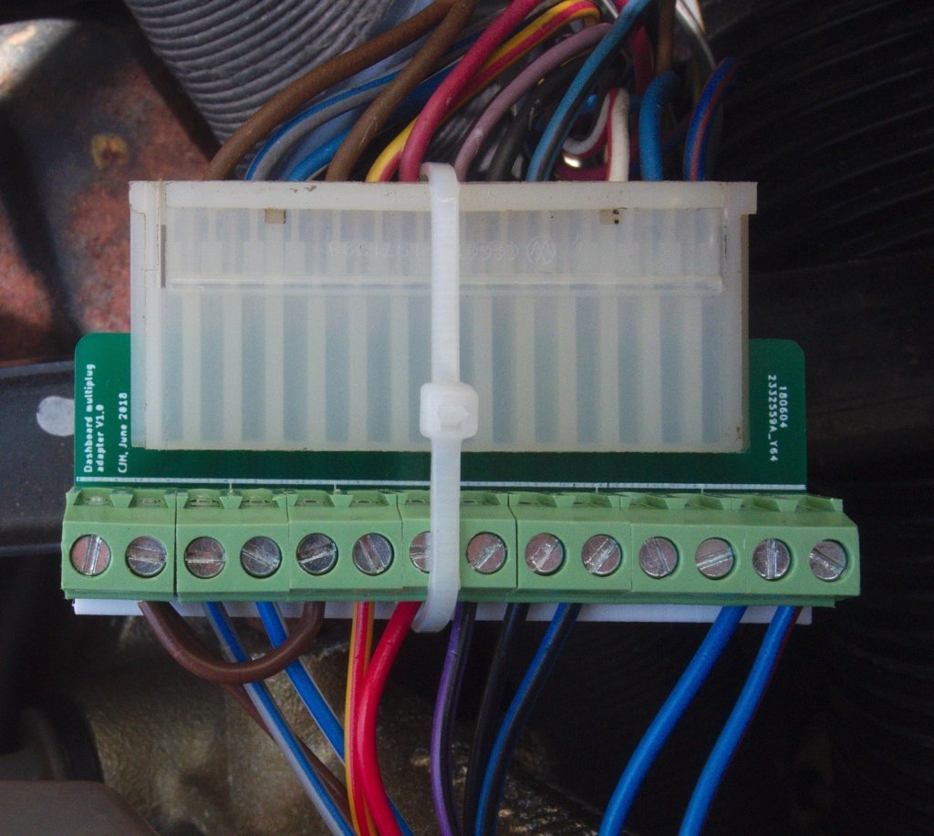
So that meant I could re-use pin 12, and I have pins 1 and 11 vacant. I connected pin 1 on my adapter board to the tachometer input on the PCB, pin 11 to the LED6 input and pin 12 to the glowplugs input. And I inserted three of my spare terminal pigtails into the corresponding slots in my multiplug, and I'm all ready for when I want to hook up my extra circuits. My multiplug is now non-standard, so I'd have to remember that if ever I wanted to put a standard foil circuit board back in, but with my replacement PCB the order of the pins is immaterial.
I'd spotted it before but put it to the back of my mind - there's a White/Red wire going into pin 12 of my multiplug. Mine's a pre-85 van, so that makes pin 12 the glowplugs pin, yet my van is a petrol van.

So I traced the White/Red wire through the loom. It ends up at a two pin plug behind the fusebox. The Red/Black wire goes to earth. So evidently unused in my van - must have been a standard fit regardless of engine type.
So that meant I could re-use pin 12, and I have pins 1 and 11 vacant. I connected pin 1 on my adapter board to the tachometer input on the PCB, pin 11 to the LED6 input and pin 12 to the glowplugs input. And I inserted three of my spare terminal pigtails into the corresponding slots in my multiplug, and I'm all ready for when I want to hook up my extra circuits. My multiplug is now non-standard, so I'd have to remember that if ever I wanted to put a standard foil circuit board back in, but with my replacement PCB the order of the pins is immaterial.
"I'm a man of means, by no means....King of the Road!"
1983 Viking Xplorer, 2.1DJ
1983 Viking Xplorer, 2.1DJ
-
CovKid
- Trader
- Posts: 8413
- Joined: 30 Apr 2006, 13:19
- 80-90 Mem No: 3529
- Location: Ralph - Coventry (Retired)
- Contact:
Re: Replacing the dashboard plastic PCB
Replacing the existing plug is no bad thing in my view. Just waiting for my 14-way one to arrive which will give extra routes into the dashpod then. Its no big deal to assemble a new plug/socket really - as long as you have the crimpers.
Roller paint your camper at home: http://roller.epizy.com/55554/" onclick="window.open(this.href);return false; for MP4 download.
-
bobby-gg
- Registered user
- Posts: 155
- Joined: 22 Oct 2012, 10:43
- 80-90 Mem No: 11794
- Location: Northumberland
Re: Replacing the dashboard plastic PCB
I'm following your thread with interest here as although I'm only suffering a little damage around the digital clock, where I've had to cut back the back lighting tracks due to damage
My real issues are my main back-light holder's have been somewhat over heated in the past, leaving them rather mid-shaped
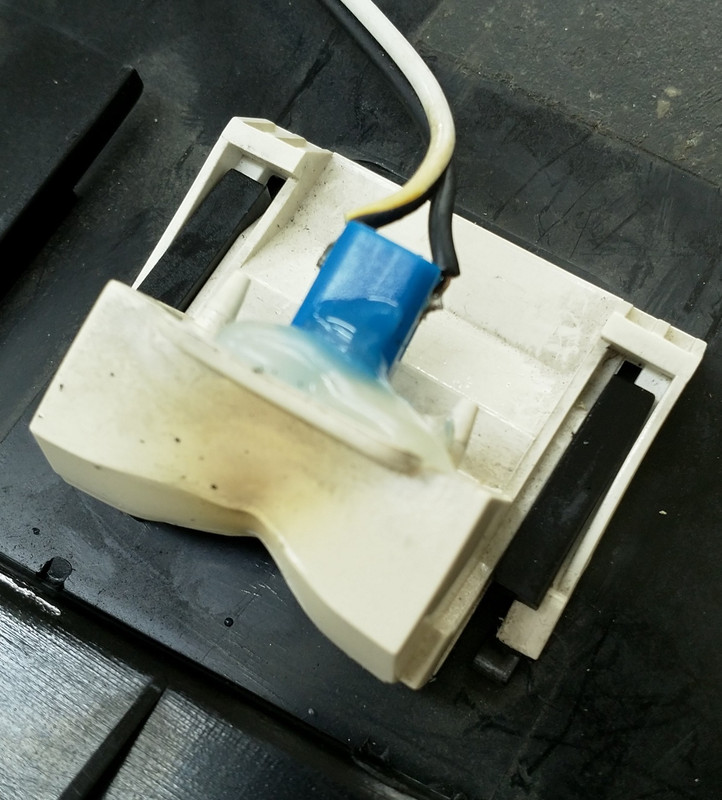
I've had to hot glue in my led's
But what I'm really interested in is the ability to wiring up the warning lights slightly differently and swap the top row with the bottom row, so those of us with smaller steering wheels, golf gti, porsche 911 etc would be able to see the indicators and main beam warning lights
From this
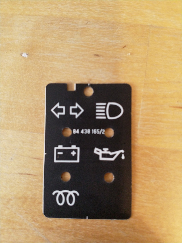
To this
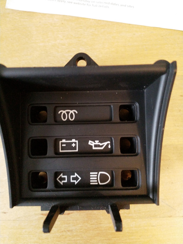
I've followed the traces on your pcb and it would just be a case of swapping over the inputs into the desired tracks
So I'd be up for a full kit
Rob
My real issues are my main back-light holder's have been somewhat over heated in the past, leaving them rather mid-shaped
I've had to hot glue in my led's
But what I'm really interested in is the ability to wiring up the warning lights slightly differently and swap the top row with the bottom row, so those of us with smaller steering wheels, golf gti, porsche 911 etc would be able to see the indicators and main beam warning lights
From this
To this
I've followed the traces on your pcb and it would just be a case of swapping over the inputs into the desired tracks
So I'd be up for a full kit
Rob
Re: Replacing the dashboard plastic PCB
Hi Rob
Yes, I think that rearrangement will work. The bottom two LEDs can be configured individually as 'switched earth' or 'switched live'. The main beam circuit is switched live, and the conventional location (top right) is hardwired this way, so can only be used for a switched live circuit, but in your arrangement it will be unused so that doesn't matter. The Indicator circuit is switched earth, and the conventional location (top left) is hardwired this way, but the glowplug circuit is also switched earth, so you can use the top left LED for that circuit.
For your wired illumination LEDs there are terminals on the PCB to connect them direct to the dimmer supply (or IGN if you prefer) and jumpers to bypass the current limiting resistors, so if your hot glued LEDs are stable and working they can be wired up without disturbing them.
"I'm a man of means, by no means....King of the Road!"
1983 Viking Xplorer, 2.1DJ
1983 Viking Xplorer, 2.1DJ
-
bobby-gg
- Registered user
- Posts: 155
- Joined: 22 Oct 2012, 10:43
- 80-90 Mem No: 11794
- Location: Northumberland
Re: Replacing the dashboard plastic PCB
CJH wrote:Hi Rob
Yes, I think that rearrangement will work. The bottom two LEDs can be configured individually as 'switched earth' or 'switched live'. The main beam circuit is switched live, and the conventional location (top right) is hardwired this way, so can only be used for a switched live circuit, but in your arrangement it will be unused so that doesn't matter. The Indicator circuit is switched earth, and the conventional location (top left) is hardwired this way, but the glowplug circuit is also switched earth, so you can use the top left LED for that circuit.
For your wired illumination LEDs there are terminals on the PCB to connect them direct to the dimmer supply (or IGN if you prefer) and jumpers to bypass the current limiting resistors, so if your hot glued LEDs are stable and working they can be wired up without disturbing them.
Thanks for the quick reply and clarification on my idea.
Put my name next on the list for a set when they are available
Rob