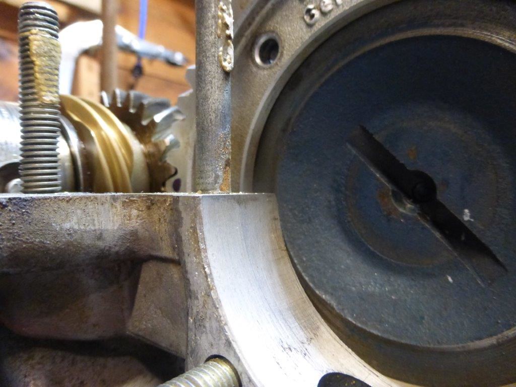
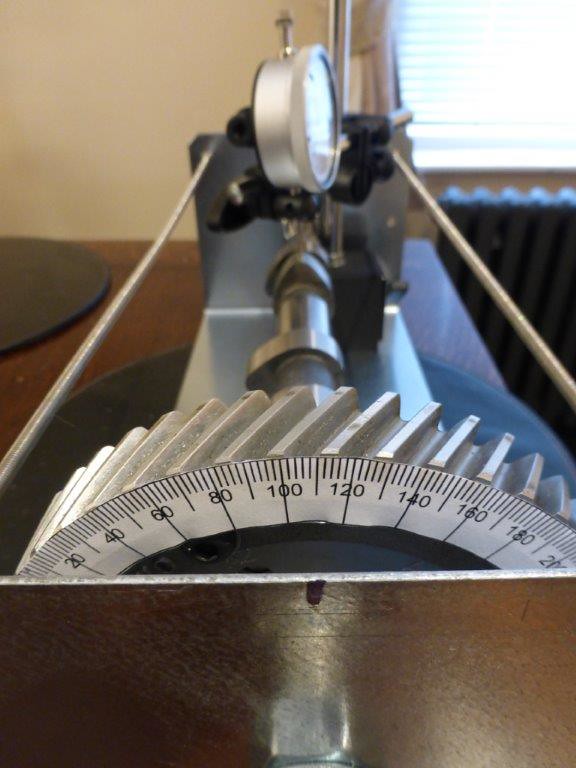
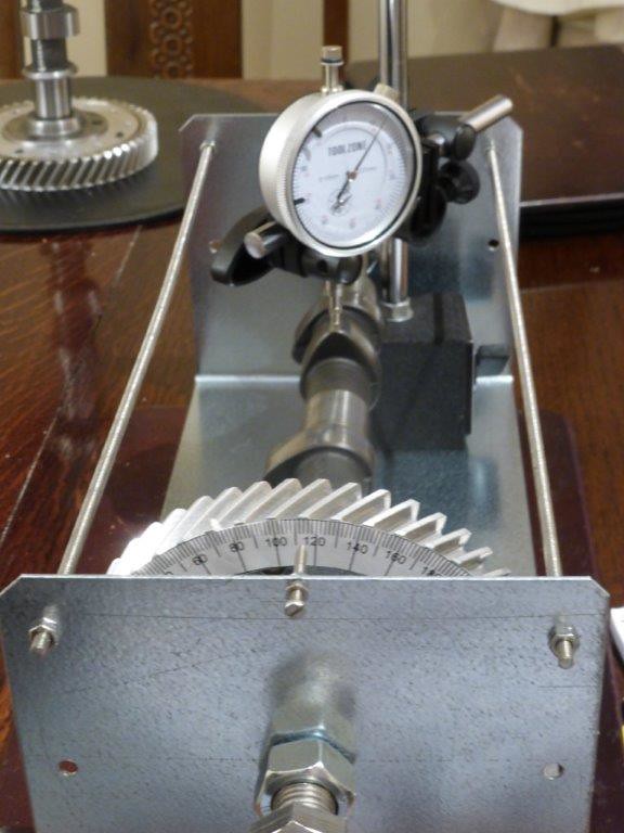
For both of the above reasons (cam=2xcrank*, TDC is marked on crank pulley) it makes sense to measure with the cam in the case, and put your measuring scale on the flywheel. I found a protractor image on the web (saved it here) and then printed it to fit the flywheel - the bigger the better, to improve your precision.
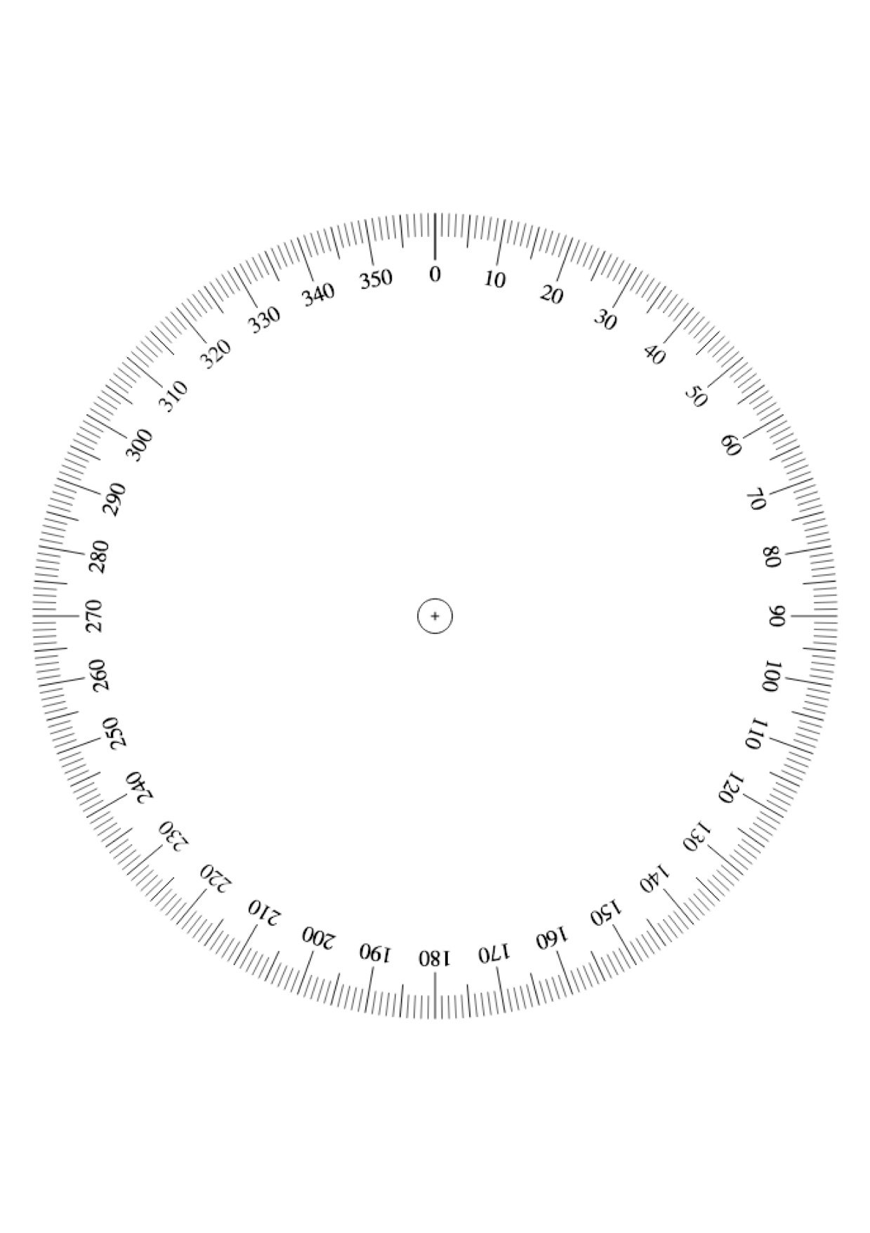
It doesn't matter about the precise orientation of the protractor image - just stick it on then record an angle when the pulley is at TDC and subtract this reading from all your measurements. I simply taped a piece of flat plastic to the case to give me a reading point - it doesn't matter where this is as long as you record the reading when you're at TDC.
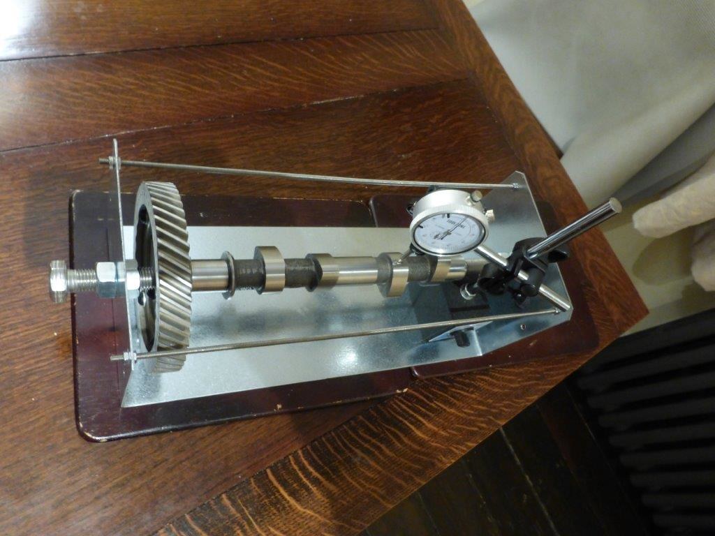
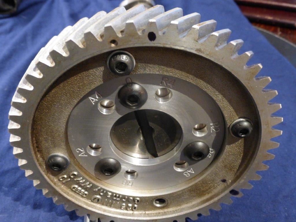
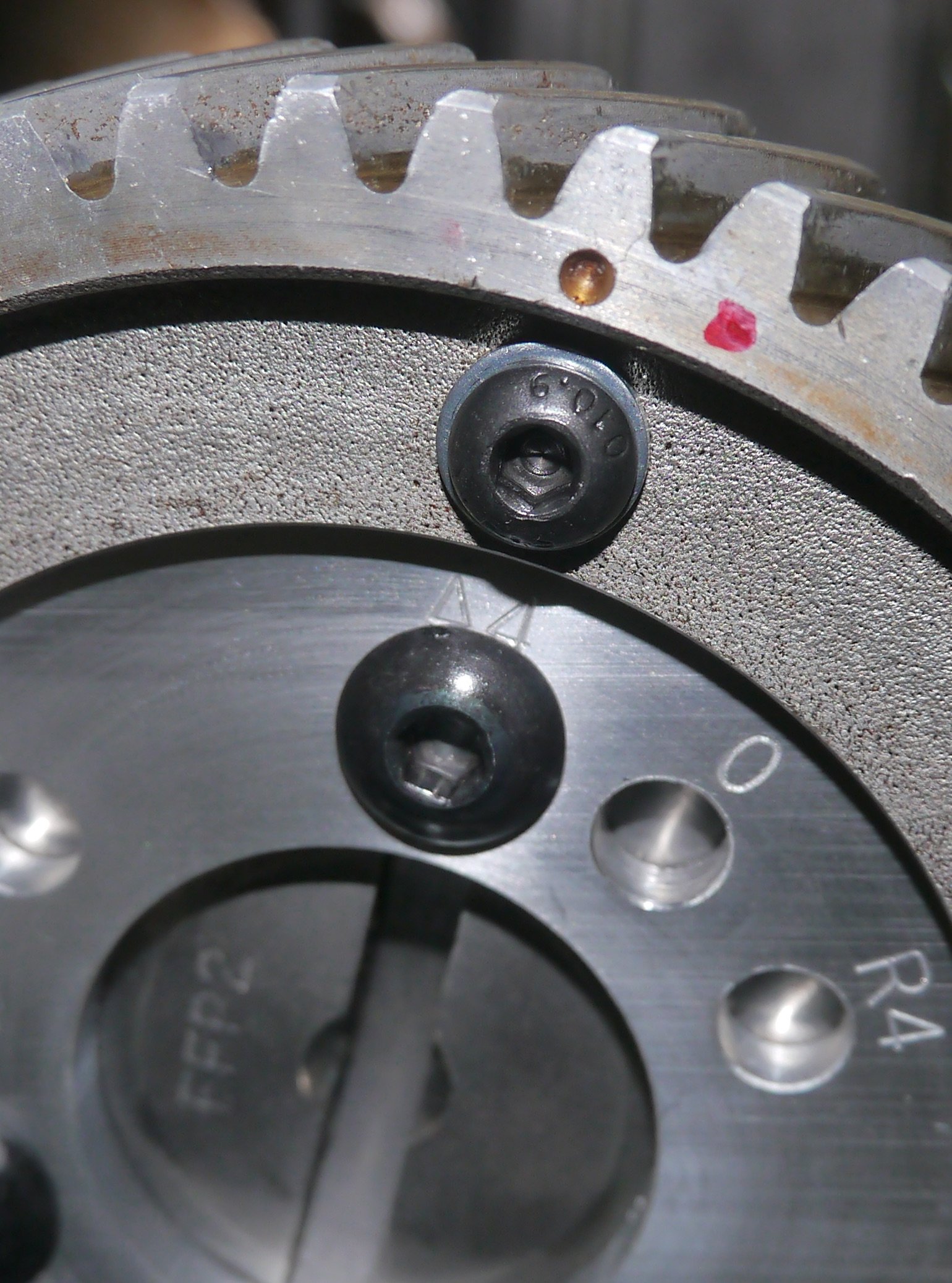
To make the measurements I dropped a tappet into the case, and another one inverted on top to give a flat surface (don't use an old dished tappet) for the dti gauge to rest on. The pushrod protector bolt holes make a good place to screw the dti gauge shaft into.
The measurements you record will need to be offset by the reading you get at TDC, then you'll need to add/subtract 360 each time your readings go past 0 - easily done in a spreadsheet.
Good luck!
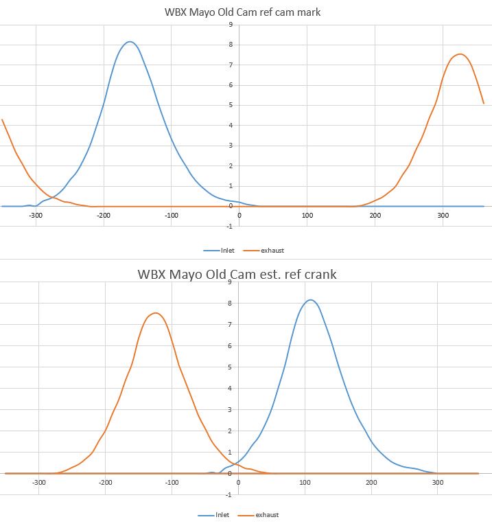
*E D I T - I got that wrong - the crank turns twice for every turn of the cam, so you'll need to multiply your cam angles by two to get crank angles. cam=0.5xcrank