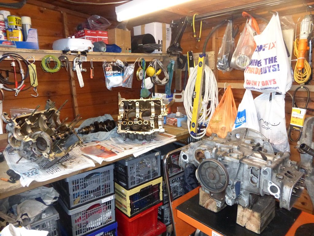
Spent a few hours this dull and wet afternoon in the shed splitting an early DG ( engine on the right is late DG) to examine the oil feed system in detail with a torch and a piece of wire to check where the drillings all go.
Very interesting

Some bit's I still don't fully understand like how the crank pulley bearing oil channel is drilled and cast

, the diagram above may be technically correct but does not describe it well, I feel an itchy diagram coming on.
Pressure relief valve vents to oil pickup pipe and not sump that's for sure so my oil temp sender is not in sump oil.
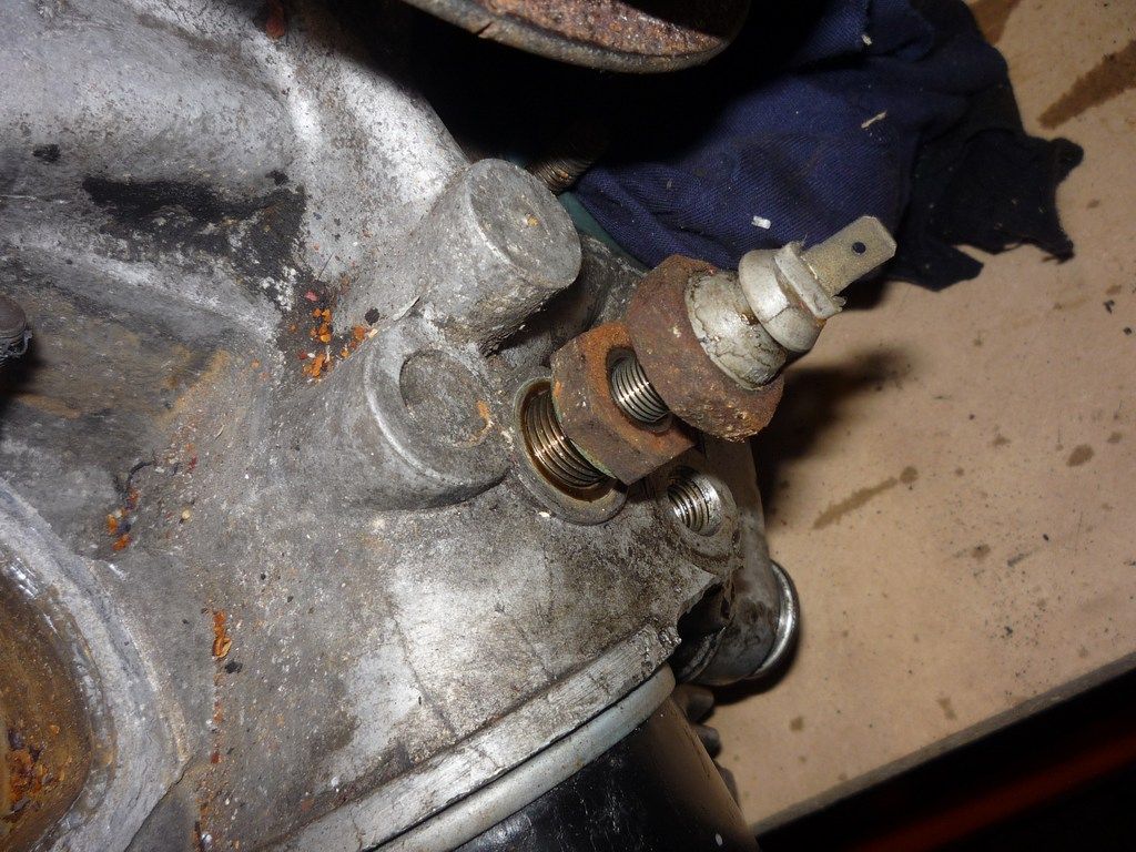
High pressure switch is in the end of the main gallery after oil filter
low pressure switch is in a lower drilling off the main gallery feeding camshaft so may suffer some pressure drop if tappets or cam bearings are worn, I'm thinking a pressure check on the high pressure switch location ( main gallery) would be very interesting to compare.