Ammeter

An alchemy of sparks, copper wire and earth

Moderators: User administrators, Moderators

User avatar
CJH
Registered user
Posts: 3018
Joined: 15 Jul 2013, 06:51
80-90 Mem No: 12576
Location: Nottingham

Ammeter

Post by CJH »

I'm looking for advice on what sort of ammeter I need to monitor current flow to/from my leisure battery, and where I should fit it.

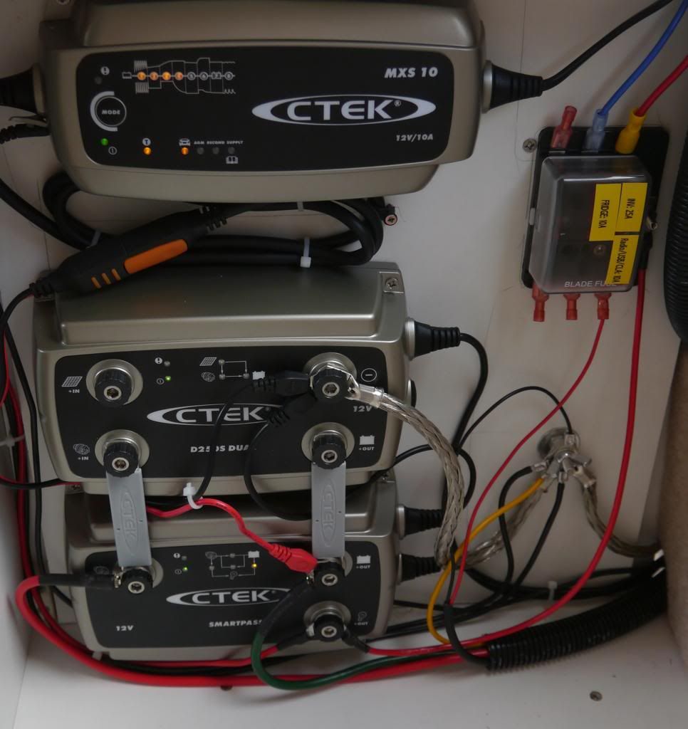
I've recently installed a CTEK charging system (which I wrote about here), and one of the things I like about it is there's now only a single cable to the leisure battery - all my 'consumers' are connected via one of the posts on the CTEK 'Smartpass'.

In the photo below, the thick green wire is the feed to/from my leisure battery, and the consumers are all connected to the post directly below that post.
Image

I've also now ordered a solar panel. The CTEK system has a built-in MPPT controller, but it has no way to view the current flow.

So I thought I'd add an ammeter. But if I try to monitor the current from the solar panel directly, then 1) that will be at the panel's voltage, so I'd need to measure that too if I want to know the power output, and 2) I'm concerned in case adding an external ammeter might affect the accuracy of the MPPT tracking, which I believe measures the current at a range of voltages. I'm probably worrying needlessly, but I don't know enough about measuring current to be confident that an external meter won't interfere.

But then I realised that what I really want to know is how much current is going into my leisure battery. So I figured that if I insert an ammeter into the leisure battery feed then I'll be able to measure the net current - if it's negative it means I'm using more current than I'm putting in, or if I turn off all the consumers I'll be able to see how much current is going in, from the solar panel, or my charger, or even the alternator.

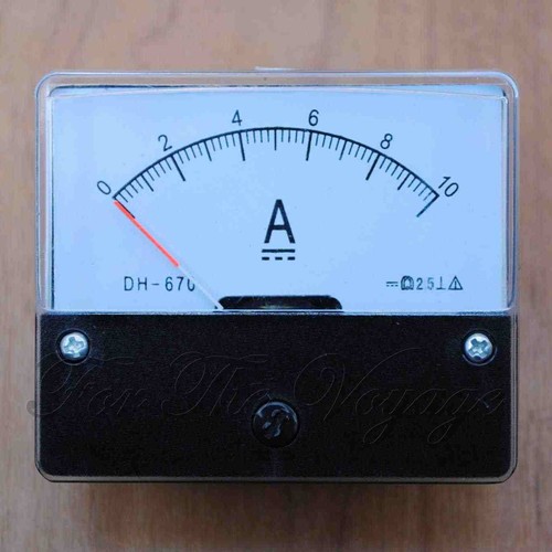
So I think I'll need an ammeter that will cope with around 50A (I've started with a 40A fuse in the leisure battery circuit, but the wiring will cope with 70A). And from what I've read ammeters that work at this sort of current use a shunt resistor. I've also read that ammeters like that tend to be placed in the earth side of the circuit, which I guess would mean mounting it in the battery box between the -ve terminal and the earth strap.

Am I on the right lines? If so, I can obviously trawl ebay for something suitable, but can anyone recommend one?
"I'm a man of means, by no means....King of the Road!"

1983 Viking Xplorer, 2.1DJ

User avatar
CJH
Registered user
Posts: 3018
Joined: 15 Jul 2013, 06:51
80-90 Mem No: 12576
Location: Nottingham

Re: Ammeter

Post by CJH »

I've just realised that putting the ammeter on the earth side would be a bit of a nuisance, since I'm planning to fit a second leisure battery via a changeover switch near the CTEK units. The two batteries would be a long way apart, so the earths wouldn't be near each other. Why is it recommended that the ammeter should be in the earth side, and would it matter if I placed it in the +ve side between the green lead and the terminal on the CTEK Smartpass?
"I'm a man of means, by no means....King of the Road!"

1983 Viking Xplorer, 2.1DJ

User avatar
CJH
Registered user
Posts: 3018
Joined: 15 Jul 2013, 06:51
80-90 Mem No: 12576
Location: Nottingham

Re: Ammeter

Post by CJH »

OK, I'm getting there slowly.

1) I think that many digital meters assume that the meter's power supply ground and the line being measured are at the same potential, so obviously connecting the shunt into the positive line instead is going to cause a problem.

2) I'm being dozy - there's an earth connection on the CTEK units, so there's no reason I can't insert the shunt in there. It'll still measure the net current in the CTEK system.

Feel free to join in. :D
"I'm a man of means, by no means....King of the Road!"

1983 Viking Xplorer, 2.1DJ

User avatar
bigherb
Registered user
Posts: 2581
Joined: 27 Mar 2008, 13:50
80-90 Mem No: 5789
Location: West Kent

Re: Ammeter

Post by bigherb »

A normal amp meter measures the magnetic field around the cable. The meters that use a shunt are in fact voltmeters measuring the voltage drop across a known distance and converting it to a amp scale, like all voltmeters it doesn't matter what it is measuring it only measures the potential difference between the the two probes.
1982 Camper 1970 1500 Beetle Various Skoda's, Ariel Arrow

User avatar
CJH
Registered user
Posts: 3018
Joined: 15 Jul 2013, 06:51
80-90 Mem No: 12576
Location: Nottingham

Re: Ammeter

Post by CJH »

bigherb wrote:A normal amp meter measures the magnetic field around the cable. The meters that use a shunt are in fact voltmeters measuring the voltage drop across a known distance and converting it to a amp scale, like all voltmeters it doesn't matter what it is measuring it only measures the potential difference between the the two probes.

Yes, that's why I was puzzled why all the meters I've found with wiring diagrams show them connected into the negative side - this one for instance. All I can think of is that it's because they also require a power supply to light the LEDs, and maybe the circuitry assumes that the potential of the shunt is the same as the negative side of the supply voltage. I've read some reviews of a few meters like this, and there are a few non-specific warnings about getting it wrong.

I looked at some clip on models too - the sort that measure magnetic field, such as this one from Durite. I've only seen these as analogue meters, and they don't claim to be particularly accurate, and since I'm hoping to be able to resolve a variation of a few amps from the solar panel I think I'd prefer a digital version with greater resolution.
"I'm a man of means, by no means....King of the Road!"

1983 Viking Xplorer, 2.1DJ

User avatar
CJH
Registered user
Posts: 3018
Joined: 15 Jul 2013, 06:51
80-90 Mem No: 12576
Location: Nottingham

Re: Ammeter

Post by CJH »

I'm still confused. I found a seller on ebay who has helpfully provided 'right' and 'wrong' diagrams for the wiring, and he makes a big thing of NOT powering the meter from the same supply that it's measuring. So it's not just that it has to measure the ground, but the supply actually has to be isolated. Not really convenient in a van where I've got one shared earth for everything. He actually shows a battery powering the meter. What's the reason for this? In the picture below he mentions 'interference', but in another of his listings he hints at damage.

E D I T: ..and if I'm going to power the meter from a little battery, then I can't see why I couldn't put the shunt in the +ve side of the circuit, since the battery would surely 'float'.

Right:
Image

Wrong:
Image
"I'm a man of means, by no means....King of the Road!"

1983 Viking Xplorer, 2.1DJ

User avatar
bigherb
Registered user
Posts: 2581
Joined: 27 Mar 2008, 13:50
80-90 Mem No: 5789
Location: West Kent

Re: Ammeter

Post by bigherb »

Probably because they are cheap meters measuring only a few millivolts they can get affected by power supply fluctuations.
The best way to do it is with a Hall chip sensor as they are non contact you can mount it where you like then.
1982 Camper 1970 1500 Beetle Various Skoda's, Ariel Arrow

User avatar
CJH
Registered user
Posts: 3018
Joined: 15 Jul 2013, 06:51
80-90 Mem No: 12576
Location: Nottingham

Re: Ammeter

Post by CJH »

Thanks Herb - I'll look into that.

I had more or less settled on buying two meters - one (like this) to show amps and volts in the solar panel circuit (and since that will be below 10A there are meters that don't require an external shunt), and one higher current version with shunt (like this) to show net current in the charging circuit. I was planning to mount these in a panel inside the wardrobe with a little battery and a push-to-make button to light them both up, so the battery would only be drained while I was pressing the button to read the meters. Interestingly, both of the ones I've linked above show circuit diagrams with a common power supply, but I think I'll still go for a battery. The problem I'm having now is finding an ammeter that specifically states that it can display negative current values - not an issue for the solar panel volt/ammeter (which should be protected against reverse current) but the net current in the charging circuit could well be negative at times.

But I think I'll just park my shopping basket for a while now, and look into hall sensor meters.
"I'm a man of means, by no means....King of the Road!"

1983 Viking Xplorer, 2.1DJ

User avatar
bigherb
Registered user
Posts: 2581
Joined: 27 Mar 2008, 13:50
80-90 Mem No: 5789
Location: West Kent

Re: Ammeter

Post by bigherb »

Perhaps Ghost can design something dedicated to your setup. Or use a hall sensor that are for oscilloscopes which work at one millivolt = one amp, you can then use any meter that reads millivolts.
1982 Camper 1970 1500 Beetle Various Skoda's, Ariel Arrow

User avatar
CJH
Registered user
Posts: 3018
Joined: 15 Jul 2013, 06:51
80-90 Mem No: 12576
Location: Nottingham

Re: Ammeter

Post by CJH »

bigherb wrote:Perhaps Ghost can design something dedicated to your setup.
Yeah, where is he when you need him?

Actually, if I'm going for my battery powered solution then I think I can handle that myself. Two cheap little meters - one directly in the solar panel circuit, one fed via a shunt in the earth side of my charging system, and a little battery with a push switch to power both meters. I think there's space in the back cover of the boxing around my Zig unit to mount the meters and the switch, and the battery could be inside the zig boxing since it should last for a very long time.

bigherb wrote:Or use a hall sensor that are for oscilloscopes which work at one millivolt = one amp, you can then use any meter that reads millivolts.
Ah, ok, thanks, good idea. I only found one hall effect dedicated power meter, and that was about £85, from Australia. Your solution sounds a lot cheaper.
"I'm a man of means, by no means....King of the Road!"

1983 Viking Xplorer, 2.1DJ

User avatar
CJH
Registered user
Posts: 3018
Joined: 15 Jul 2013, 06:51
80-90 Mem No: 12576
Location: Nottingham

Re: Ammeter

Post by CJH »

I'm considering going 'old school'.

Perhaps these two for the voltage and current from the solar panel:
Image
Image

and maybe this one for the current going to/from the leisure battery:
Image

Just waiting to hear whether that last one will pass higher currents without damage.
"I'm a man of means, by no means....King of the Road!"

1983 Viking Xplorer, 2.1DJ

Plasticman
Trader
Posts: 8072
Joined: 12 Oct 2005, 20:55
80-90 Mem No: 1948
Location: lincolnshire

Re: Ammeter

Post by Plasticman »

Most of the old sports classics I worked on Yeats back had ammeters,they were connected in series ,bit the had to be able to take all the output from the dynamo as was in those days ,so in your case all.cabling inc the meter has to be able to carry your max current plus a margin
mm

User avatar
CJH
Registered user
Posts: 3018
Joined: 15 Jul 2013, 06:51
80-90 Mem No: 12576
Location: Nottingham

Re: Ammeter

Post by CJH »

metalmick8y wrote:Most of the old sports classics I worked on Yeats back had ammeters,they were connected in series ,bit the had to be able to take all the output from the dynamo as was in those days ,so in your case all.cabling inc the meter has to be able to carry your max current plus a margin
mm

Yes, in fact that's the problem with the analogue version in my post above - and as I didn't fancy running too much chunky cable to a place where I could mount the meter I've opted for the digital meters instead.

This one for the net current flow in the charging circuit:
Image
The advantage over the analogue meter is that it uses a shunt (which I'll place in the earth side of the circuit, which means all the exposed connections are at earth potential) so the cabling from the shunt to the meter itself connects to those little screws and doesn't have to cope with the full circuit load - it just has to be thick enough and short enough to have minimal voltage drop. The shunt supplied with this meter is rated to 100A, which gives me plenty of margin - even if the full output of my 40A alternator AND my 10A charger AND my 5A panel was going into the leisure battery I'd be safe.

I've gone for this one for the solar panel circuit - nice yellow digits to go with it being a measure of the sun :D :
Image
This one will operate at below 10A so doesn't use an external shunt. This means that I'll have to connect it in series with the solar panel, but since the wiring for that isn't so thick that'll be easy enough to do.
"I'm a man of means, by no means....King of the Road!"

1983 Viking Xplorer, 2.1DJ

User avatar
ghost123uk
Registered user
Posts: 6855
Joined: 10 Mar 2006, 10:15
80-90 Mem No: 2585
Location: John in Malpas, in the very S. W. part of Cheshire.
Contact:

Re: Ammeter

Post by ghost123uk »

CJH wrote:
bigherb wrote:Perhaps Ghost can design something dedicated to your setup.
Yeah, where is he when you need him?
.

Hello, Ghost here :roll:

Your not going to like it :wink:

Firstly, avoid digital shunt meters unless you are prepared to pay big bucks. The reason they need a shunt in the -ve line and a separate supply is that they are cr@p design (cheap).

Secondly, although I have been "into" electronics since I was 5 (literally) and my van is full of gadgets, I do not have any ammeters :shock: You just don't need them. Let me give my tuppence worth. What I HAVE done is use my (decent) multimeter on quite a few occasions (it passes the time at meets, during the day when you are sober :shock: :shock: ) to measure current in and out. Do it on your solar panel when it is pointed at a hot sun, make a mental note of current going into the leisure when it is somewhat depleted (say 12.2 volts). Then do the same on a dull day. Mine is ~4 amps in full sun and as little as .2 amp on a cloudy day.

Then do some tests on consumers and note what they take.

Then forget about it :wink:

It's the voltage at the leisure battery that is all important.

If it is low, and you have a panel pointing at a bright sun, you already know from your tests that it will be chucking xx amps in.

OK, I know you want "stuff" in there 8) as shown by your recent (very nice) bits of kit 8) (watch out for those exposed live terminals / bus bars by the way :wink: ) So, if it were I, I would for sure go for your "old skool" approach and use simple, reliable, easy to read analogue meters.

Or do as I do and just occasionally use your multimeter, you soon get bored of checking it as you soon know what reading you are going to get !!

E D I T = just seen your last post, actually that one for the solar panel looks quite cute. I wonder what it's own current draw is ? (some are quite high) Will you be putting a switch in ? (to turn it off) If so, I guess doing so would isolate the panel :shock: Also note = check the calibration of any / all meters with a known good multimeter. Half a volt out is quite a lot when measuring charging voltages (between 12 volts and 14.5 volts) and I have seen (and got) panal meters that are at least that far out :evil:
Got a new van, but it's a 165bhp T4 [shock horror] Accurate LPG Station map here

User avatar
CJH
Registered user
Posts: 3018
Joined: 15 Jul 2013, 06:51
80-90 Mem No: 12576
Location: Nottingham

Re: Ammeter

Post by CJH »

Thanks Ghost

I completely agree with you that I don't need these meters at all! With a little bit of experimenting with my multimeter I'll soon have a good idea what's going on. I took the same approach once I realised what it would cost to add a tachometer dash - by calculating speed versus revs I now know enough about what my engine is doing to not need one.

But my interest is in learning more about what the MPPT controller and battery management system are doing with the solar energy. That's one thing missing from the setup IMO. The analogue meters were nice, but I couldn't really justify another 3 x £15 for something I don't really need. So the cheapo Chinese digital meters will have to do. In fact, since they're coming from China I'm fully expecting to have my panel wired up and running long before they arrive, so yes, I'll probably already know all about what's happening in the system!

Those two digital meters need an isolated power supply, so I'm planning to put in a little battery holder and a push-to-make switch that will turn the meters on when I want to look at the readings. So the battery will last for a very long time I expect. I must admit I hadn't thought about whether the solar panel meter would disconnect the panel itself if the meter itself isn't powered. Is that likely do you think? I'm hoping there's a built-in shunt that would pass current even if the electronics to measure the current aren't powered. If not I'll have to think again. I'll do some testing obviously before I start any installation.

By the way, thanks for the warning about the exposed terminals on the fuse box. That's actually the reason I put the insulated spades on the unused terminals, before I realised that they're not live unless there are fuses in the slots - D'Oh! But yes, the feed from the LVD is exposed, albeit difficult to touch accidentally, but it's a risk and I should do something to insulate it better.
"I'm a man of means, by no means....King of the Road!"

1983 Viking Xplorer, 2.1DJ

Locked