
Headlight upgrade comparative diagram (for peer review)
Moderators: User administrators, Moderators
-
Hacksawbob

- Registered user
- Posts: 4445
- Joined: 11 Oct 2005, 07:11
- 80-90 Mem No: 1168
- Location: Lancs UK member 1168
Headlight upgrade comparative diagram (for peer review)
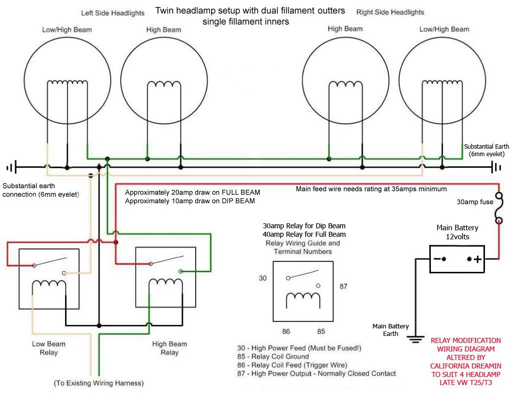
I am getting a bit obsessional about wiring lately, So I did this diagram hopefully to weigh up the various relay upgrade options (and for myself to understand a bit better before I go cutters in hand to the fuse box! ) If anyone has anything to add (or remove) let me know before I add it to the wiki which is getting a bit out of date on the subject and could do with a revamp.
member 1168
-
California Dreamin
- Registered user
- Posts: 2673
- Joined: 03 Apr 2007, 12:54
- 80-90 Mem No: 8386
- Location: Nottingham
Re: Headlight upgrade comparative diagram (for peer review)
Really good work....and gives a good basic description of the PRO'S & CONS.
The only thing I noticed...and you have me checking my own understanding of this....is why 4 relays are needed on B & C.
My diagram has two but with full beam using a 40 amp for some built in safety.
Now the only thing I need to check is the switch supply side for FULL BEAM....as I understand this has to be taken from one particular position in order to keep the blue tell tail lamp working on the dash...I've forgotten..
Martin
1989 California 2.1MV
-
Titus A Duxass

- Registered user
- Posts: 5777
- Joined: 24 Nov 2007, 08:22
- 80-90 Mem No: 4475
- Location: Cologne
Re: Headlight upgrade comparative diagram (for peer review)
I have a slight variation on both of those.
I use four 30 amp relays (overkill but I get them free), these are paired and each pair gets its own 12v feed.
The relays are driven by original feeds that go to the bulbs.
I bought bulb connectors and spades that go into the original bulb connectors.
The relay pairs are mounted directly behind the headlights.
VW T3 GTi Camper 2,0l
-
California Dreamin
- Registered user
- Posts: 2673
- Joined: 03 Apr 2007, 12:54
- 80-90 Mem No: 8386
- Location: Nottingham
Re: Headlight upgrade comparative diagram (for peer review)
With around 20 amps flowing when all four lamps illuminate on full beam, a single 40 amp relay should be fine, although if you're getting them for free lol.
Approx 10 amps on dip (2 X 55watts) ... and around 20amps on full (2 X 55 watts plus 2 X 60) which is why I chose a 30 amp relay for dip, 40 for full giving plenty of overhead.
The main positive feed needs to take into account Voltage Drop over the 2 - 3 metres of wire so again double the rating at least.....(40amp plus wiring)
And
Don't forget...what is done for the feed needs copying for the earths, so substantial and one each side onto bare metal.
Martin
Last edited by California Dreamin on 26 Apr 2012, 09:03, edited 1 time in total.
1989 California 2.1MV
-
Titus A Duxass
- Registered user
- Posts: 5777
- Joined: 24 Nov 2007, 08:22
- 80-90 Mem No: 4475
- Location: Cologne
Re: Headlight upgrade comparative diagram (for peer review)
California Dreamin wrote: Don't forget...what is done for the feed needs copying for the earths, so substantial and one each side onto bare metal.
Martin
Good point, a lot of people forget this.
Mine are 6 mm2 and as short as possible.
VW T3 GTi Camper 2,0l
-
Titus A Duxass
- Registered user
- Posts: 5777
- Joined: 24 Nov 2007, 08:22
- 80-90 Mem No: 4475
- Location: Cologne
Re: Headlight upgrade comparative diagram (for peer review)
California Dreamin wrote:With around 20 amps flowing when all four lamps illuminate on full beam a single 40 amp relay should be fine although if you're getting them for free lol.
Martin
Unfortunately try as I might I could'nt "find" a 40 amp relay, it was 30 amp or nothing.
VW T3 GTi Camper 2,0l
-
California Dreamin
- Registered user
- Posts: 2673
- Joined: 03 Apr 2007, 12:54
- 80-90 Mem No: 8386
- Location: Nottingham
Re: Headlight upgrade comparative diagram (for peer review)
£2.25 posted......you are right, they are becoming more difficult to find, most are 5pin.
http://www.ebay.co.uk/itm/12V-40A-4-Pin ... 3f163ba066" onclick="window.open(this.href);return false;
Martin
http://www.ebay.co.uk/itm/12V-40A-4-Pin ... 3f163ba066" onclick="window.open(this.href);return false;
Martin
1989 California 2.1MV
-
Hacksawbob
- Registered user
- Posts: 4445
- Joined: 11 Oct 2005, 07:11
- 80-90 Mem No: 1168
- Location: Lancs UK member 1168
Re: Headlight upgrade comparative diagram (for peer review)
Titus mounting the relays on the headllight cavity is location C on my diagram, did you do this to fit higher wattage bulbs? Have you gat a picture I can use?
member 1168
-
Titus A Duxass
- Registered user
- Posts: 5777
- Joined: 24 Nov 2007, 08:22
- 80-90 Mem No: 4475
- Location: Cologne
Re: Headlight upgrade comparative diagram (for peer review)
Hacksawbob wrote:Titus mounting the relays on the headllight cavity is location C on my diagram, did you do this to fit higher wattage bulbs? Have you gat a picture I can use?
Unfortunately I do not have a picture.
They are mounted to the body work by a self tapper, when you look into the area you can see the best place for them.
I was going to use a relay socket but it was too tight, I ended up using good quality crimps and heatshrink.
They've been installed for about 5 year now.
It got bit tight when I fitted the SA grill but there's just enough room.
I did the upgrade to get the best out of the standard bulbs and to take the pressure off the aging switch gear.
I upgraded to better standard bulbs later but not higher wattage as they are not easy to get hold of out here.
VW T3 GTi Camper 2,0l
-
Hacksawbob
- Registered user
- Posts: 4445
- Joined: 11 Oct 2005, 07:11
- 80-90 Mem No: 1168
- Location: Lancs UK member 1168
Re: Headlight upgrade comparative diagram (for peer review)
Thanks for the diagram Martin, I wasn't quite sure where those relays were going is that between stalk and fusebox position A? I think from memory on the original thread you are of the replace old wiring with new school of thought.
I had a look at the wiring diagram the main beam telltale is fed from the RHS mains and is linked in between Fuse 9 and C16 so if you are doing a total rewire post stalk it would need a connection to the blue white on wire No. 2 of the 14 pin dash multiplug.
I haven't even looked at the dim dip thing yet! (not an issue for an Austrian van )
)
the green wire looks like its supplying all 4 high beam lights, If you are pre fuse box with your relays then that supply is split between fuse 9 and 10 so the white and blackwhite wires are sharing the amps so 115 watts going through each wire = 9.5 Amps. Or are you totally rewiring over to new and missing the fusebox out altogether?and around 20amps on full (2 X 55 watts plus 2 X 60)
I had a look at the wiring diagram the main beam telltale is fed from the RHS mains and is linked in between Fuse 9 and C16 so if you are doing a total rewire post stalk it would need a connection to the blue white on wire No. 2 of the 14 pin dash multiplug.
I haven't even looked at the dim dip thing yet! (not an issue for an Austrian van
member 1168
-
California Dreamin
- Registered user
- Posts: 2673
- Joined: 03 Apr 2007, 12:54
- 80-90 Mem No: 8386
- Location: Nottingham
Re: Headlight upgrade comparative diagram (for peer review)
Hacksawbob wrote:Thanks for the diagram Martin, I wasn't quite sure where those relays were going is that between stalk and fusebox position A? I think from memory on the original thread you are of the replace old wiring with new school of thought.
the green wire looks like its supplying all 4 high beam lights, If you are pre fuse box with your relays then that supply is split between fuse 9 and 10 so the white and blackwhite wires are sharing the amps so 115 watts going through each wire = 9.5 Amps. Or are you totally rewiring over to new and missing the fusebox out altogether?and around 20amps on full (2 X 55 watts plus 2 X 60)
I had a look at the wiring diagram the main beam telltale is fed from the RHS mains and is linked in between Fuse 9 and C16 so if you are doing a total rewire post stalk it would need a connection to the blue white on wire No. 2 of the 14 pin dash multiplug.
I haven't even looked at the dim dip thing yet! (not an issue for an Austrian van
I should be ashamed of myself really but with everything else I've never got around to doing mine....so I've just ordered a relay and it's next on my list.
From memory...and the reason I'm sure this is right is from someone doing the same on a Teckie meet...the blue tell tale works if the RHS full beam feed is used to trigger the 40amp full beam relay.
My thoughts were to have all the wiring behind the headlamps (suitably insulated of course) using the original wiring only to trigger the relays. The only new wire going into the vehicle being a 4.00mm2 40amp fused feed directly attached to the starter battery positive terminal.
I am even tempted to try this without cutting the original wires or terminals, although this won't be as neat the circuit can always be returned to original.
I appreciate that this isn't the only way of doing this...it's another way and other uses may prefer using the existing wiring.
Martin
1989 California 2.1MV
-
Hacksawbob
- Registered user
- Posts: 4445
- Joined: 11 Oct 2005, 07:11
- 80-90 Mem No: 1168
- Location: Lancs UK member 1168
Re: Headlight upgrade comparative diagram (for peer review)
Yes another one on the never to do list. Ah OK so you are in the headlight cavity brigade, I'll not shoot you down for having a different opinion! 
Ok looking again.. so you can use the black/white wire for the RHS (keeping telltale) as the switch to fire the main beams and maybe yellow/black for the dipped then isolate the redundant white and yellow wires.
The existing wiring doesn't have a lot of overhead agreed (0.5 amp) but adequate for legal bulbs. By using only the 2 relays you are concentrating the amps resulting in the need for the 40AMP relays and beefier wires, Is there a space issue behind there having 4 relays (less than I thought from Titus' post) or is it tidier/cheaper/quicker having 2?
You put your eggs in one basket this way, if there is a problem and you loose the fuse at the battery you loose all lights in one hit
 The stock setup has some redundancy, its unlikely that you will loose all four at once.
For the non cutting version I'd like to try this too, maybe crimping a terminal that goes onto the flasher stalk (not sure how this connects though) and then the other end (now fed from a P terminal via relay) that goes into the a21 and b22 in the back of the fuse box, my problem is I cant find those round connectors in the terminal blocks or an easy way to remove what's in there. Any ideas?
Ok looking again.. so you can use the black/white wire for the RHS (keeping telltale) as the switch to fire the main beams and maybe yellow/black for the dipped then isolate the redundant white and yellow wires.
The existing wiring doesn't have a lot of overhead agreed (0.5 amp) but adequate for legal bulbs. By using only the 2 relays you are concentrating the amps resulting in the need for the 40AMP relays and beefier wires, Is there a space issue behind there having 4 relays (less than I thought from Titus' post) or is it tidier/cheaper/quicker having 2?
You put your eggs in one basket this way, if there is a problem and you loose the fuse at the battery you loose all lights in one hit
For the non cutting version I'd like to try this too, maybe crimping a terminal that goes onto the flasher stalk (not sure how this connects though) and then the other end (now fed from a P terminal via relay) that goes into the a21 and b22 in the back of the fuse box, my problem is I cant find those round connectors in the terminal blocks or an easy way to remove what's in there. Any ideas?
member 1168
-
California Dreamin
- Registered user
- Posts: 2673
- Joined: 03 Apr 2007, 12:54
- 80-90 Mem No: 8386
- Location: Nottingham
Re: Headlight upgrade comparative diagram (for peer review)
Hmmmm yes....there are flaws in each of the methods.
Once the main positive feed is attached to the bigger of the two relays it would then loop to feed the second but from there on in the ouputs wouldn't need to be as heavy....but there in lies a problem, if a fault were to occur with the lighter gauge wire it would melt and burn that wiring without blowing the main supply fuse. the only way to safe gaurd against this would be to have each of the outputs from the relays fused as well .
Martin
Once the main positive feed is attached to the bigger of the two relays it would then loop to feed the second but from there on in the ouputs wouldn't need to be as heavy....but there in lies a problem, if a fault were to occur with the lighter gauge wire it would melt and burn that wiring without blowing the main supply fuse. the only way to safe gaurd against this would be to have each of the outputs from the relays fused as well
Martin
1989 California 2.1MV
-
Hacksawbob
- Registered user
- Posts: 4445
- Joined: 11 Oct 2005, 07:11
- 80-90 Mem No: 1168
- Location: Lancs UK member 1168
Re: Headlight upgrade comparative diagram (for peer review)
Well you could use the fused 30 amp relays (I cant find 40 amp fused relays) but then of course all the high beam with a single relay may be pushing it so back to square one. Plus the fuse socket will increase the possibility of moisture ingress. The high beams will only ever pull 20amps so you've got plenty of headroom on a 30amp relay daisy chain the positve feeds so there is no one point of falure. I cant help thinking your over-engineering it without the benefit though. I am drawn to the simple elegance of the two relay post stalk setup (and cost!)
member 1168
-
jamesc76

- Registered user
- Posts: 6241
- Joined: 14 Oct 2005, 14:42
- 80-90 Mem No: 1186
- Location: Nottingham
- Contact:
Re: Headlight upgrade comparative diagram (for peer review)
I did my t4 and used a relay for each light, that way if relay fails you dont loose all the lights! ie all main or all dipped!
DJ at Dubdayz Summerfest
Now cutting about in an LT35 MWB
Now cutting about in an LT35 MWB