
so nearly started today but ended up wiring in he fog lights instead!!
That nice Oldie Goodie has set me straight mostly. Am T-ing into fuel feed line before filter , however , being a syncro i cant see "kcoc" all as to where pipes go.
Would it be acceptable to T in immediately before filter in engine bay?
Failing that , once the hose dissapears from engine bay wheredoes it go to?
In the NSR wheel arch i an see sender with a pipe in it - is this flow or return?
As thinking T =ing from engine bay would be best as shortest/tidiest/safest ru of hose. The logical place to mount eber is under the rear seat on the only flat pressing in the floor (OS/near to slider on LHD) - i can mount the pump on inner seal/beam and it leass than 3ft of fuel line from pump toT.
Ideas?
One last eber Q.........
Moderators: User administrators, Moderators
-
Oldiebut goodie

- Registered user
- Posts: 7528
- Joined: 18 Apr 2008, 01:19
- 80-90 Mem No: 11135
- Location: Eastern Angle
Re: One last eber Q.........
Elvis - I'll do the remote switching here then others can see what to do.
How to use a remote control to switch on your Webasto/Eberspacher.
For this you need your timer! plus a RF Wireless Electric Garage Gate Door Remote Control available from Ebay at a price of £3.79 from China (as at Oct 2010)
Like these.


Start to disassemble the timer control. It should be self evident how they come apart - usually a couple of screws and clips.
Using the last of the three timers shewn above (the Eberspacher combitimer is exactly the same, or it could just carry the Hella markings)

Twist and remove the bulb.

Separate the two halves by depressing the lugs.
Slide out the metal retaining clips under which are hidden four more lugs that retain the module inside the casing.
The instant heat button is loose so make sure you are ready for it to drop on the floor! The variable heat knob is also loose at this point.
Undo the two screws that hold the lcd module to the rest of the unit

Separate the three pieces - they are held together now by the multi - pin connector, and lift away the button strip.
On this timer the instant heat button acts on two contacts - some are on just one. What we need is a point away from the contact areas where we can solder two fine wires that are going to lead to the remote control relay.(In this timer at the points indicated) Ensure that they enter from the back as it enables easier exiting from the rear of the timer.


That is all that needs to be done with the timer - it will differ on the various models as to where the contacts are - just ensure that you keep away from the contact pads when you make the connections.


Reassemble the unit feeding the two wires through the rear of the housing ensuring that the heat control is in the correct position as regards it's limit and the marking on the face of the unit and the heat button is the right way up. Replace the bulb.
The remote unit has three sets of terminals - 12v + &-, relay1 and relay2. Connect up the 12v supply and the two wires from the timer will go to one of the relay pairs. (they each relate to buttons A & B on the remote control) There are no polarity worries on the two wires from the timer - they just make a connection simulating the pressing of the instant heat button.
Connect the timer back up to the heater and test. The remotes have a range up to 20 metres according to their specs but 15m seems OK then starts to tail off. Just press and hold the remote button for a couple of seconds and then release to actuate the firing up or down of the heater.
If you want a greater range you will have to go to switching by mobile phone.
To do this you will need to construct a Velleman Mobile phone operated switch - part no: Velleman type MK160 this is available from several sources such as http://www.rapidonline.com/Educational- ... /74248/kw/ (around £7) or http://www.electronicprojectsonline.co. ... L-MK160and (around £10) and have a mobile phone that lights up when it is rung as the switch works by sensing the light given off by the phone. It is a fiddly construction but not that difficult.

These need to be mounted in a light tight enclosure and the relay connected to the two wires from the timer. The relay remains actuated whilst the phone is being rung and is lit up.
If anyone has the ability of adding this to the wiki I have it as a 5Mb rtf word file.
How to use a remote control to switch on your Webasto/Eberspacher.
For this you need your timer! plus a RF Wireless Electric Garage Gate Door Remote Control available from Ebay at a price of £3.79 from China (as at Oct 2010)
Like these.
Start to disassemble the timer control. It should be self evident how they come apart - usually a couple of screws and clips.
Using the last of the three timers shewn above (the Eberspacher combitimer is exactly the same, or it could just carry the Hella markings)
Twist and remove the bulb.
Separate the two halves by depressing the lugs.
Slide out the metal retaining clips under which are hidden four more lugs that retain the module inside the casing.
The instant heat button is loose so make sure you are ready for it to drop on the floor! The variable heat knob is also loose at this point.
Undo the two screws that hold the lcd module to the rest of the unit
Separate the three pieces - they are held together now by the multi - pin connector, and lift away the button strip.
On this timer the instant heat button acts on two contacts - some are on just one. What we need is a point away from the contact areas where we can solder two fine wires that are going to lead to the remote control relay.(In this timer at the points indicated) Ensure that they enter from the back as it enables easier exiting from the rear of the timer.
That is all that needs to be done with the timer - it will differ on the various models as to where the contacts are - just ensure that you keep away from the contact pads when you make the connections.
Reassemble the unit feeding the two wires through the rear of the housing ensuring that the heat control is in the correct position as regards it's limit and the marking on the face of the unit and the heat button is the right way up. Replace the bulb.
The remote unit has three sets of terminals - 12v + &-, relay1 and relay2. Connect up the 12v supply and the two wires from the timer will go to one of the relay pairs. (they each relate to buttons A & B on the remote control) There are no polarity worries on the two wires from the timer - they just make a connection simulating the pressing of the instant heat button.
Connect the timer back up to the heater and test. The remotes have a range up to 20 metres according to their specs but 15m seems OK then starts to tail off. Just press and hold the remote button for a couple of seconds and then release to actuate the firing up or down of the heater.
If you want a greater range you will have to go to switching by mobile phone.
To do this you will need to construct a Velleman Mobile phone operated switch - part no: Velleman type MK160 this is available from several sources such as http://www.rapidonline.com/Educational- ... /74248/kw/ (around £7) or http://www.electronicprojectsonline.co. ... L-MK160and (around £10) and have a mobile phone that lights up when it is rung as the switch works by sensing the light given off by the phone. It is a fiddly construction but not that difficult.
These need to be mounted in a light tight enclosure and the relay connected to the two wires from the timer. The relay remains actuated whilst the phone is being rung and is lit up.
If anyone has the ability of adding this to the wiki I have it as a 5Mb rtf word file.
1.6D 2019 VW T-Cross
200hp VW T6
1̶Y̶ ̶1̶9̶8̶7̶ ̶H̶i̶-̶t̶o̶p̶ ̶C̶a̶r̶a̶v̶e̶l̶l̶e̶
5̶0̶8̶d̶ ̶M̶e̶r̶c̶
200hp VW T6
1̶Y̶ ̶1̶9̶8̶7̶ ̶H̶i̶-̶t̶o̶p̶ ̶C̶a̶r̶a̶v̶e̶l̶l̶e̶
5̶0̶8̶d̶ ̶M̶e̶r̶c̶
-
Oldiebut goodie
- Registered user
- Posts: 7528
- Joined: 18 Apr 2008, 01:19
- 80-90 Mem No: 11135
- Location: Eastern Angle
Re: One last eber Q.........
There should be no problem teeing from by the filter so long as you can satisfy the criteria from the manual - you can have up to 20 ft of piping after the pump but it must be angled upwards throughout (and the pump also) so needs to be mounted as low as possible to make it easy. It is better to keep the length of piping from the fuel supply as short as possible.(6 ft max). It shouldn't draw the fuel from the filter as the lines and shut off solenoid should be airtight leaving the only flow direction being from the tank. Ensure that any connections are butted together as shewn in the manual otherwise an air bubble can lodge there and restrict the fuel flow and therefore the heat output.
Someone with a syncopated van will have a better idea as to the fuel line routing and possible tapping points.
Someone with a syncopated van will have a better idea as to the fuel line routing and possible tapping points.
1.6D 2019 VW T-Cross
200hp VW T6
1̶Y̶ ̶1̶9̶8̶7̶ ̶H̶i̶-̶t̶o̶p̶ ̶C̶a̶r̶a̶v̶e̶l̶l̶e̶
5̶0̶8̶d̶ ̶M̶e̶r̶c̶
200hp VW T6
1̶Y̶ ̶1̶9̶8̶7̶ ̶H̶i̶-̶t̶o̶p̶ ̶C̶a̶r̶a̶v̶e̶l̶l̶e̶
5̶0̶8̶d̶ ̶M̶e̶r̶c̶
-
Gandalf

- Registered user
- Posts: 591
- Joined: 07 Oct 2009, 18:52
- 80-90 Mem No: 7510
- Location: Southampton
Re: One last eber Q.........
I think you are a suspect terrorist Oldiebut Goodie.
1989 California Pop Top.
-
jed the spread
- Trader
- Posts: 9020
- Joined: 09 Oct 2005, 17:31
- 80-90 Mem No: 1967
- Location: Sutton in'it Syncronaut: 123
- Contact:
Re: One last eber Q.........
ELVIS wrote:rn?
As thinking T =ing from engine bay would be best as shortest/tidiest/safest ru of hose. The logical place to mount eber is under the rear seat on the only flat pressing in the floor (OS/near to slider on LHD) - i can mount the pump on inner seal/beam and it leass than 3ft of fuel line from pump toT.
Ideas?
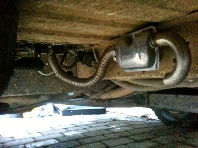
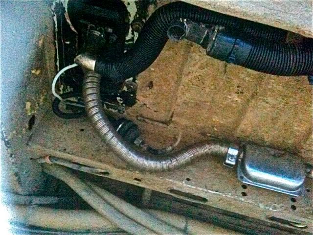
I took the Propex I had fitted out a week or so ago and fitted a D2 Airtrontic Eber instead. This is how it went in from the underneath,
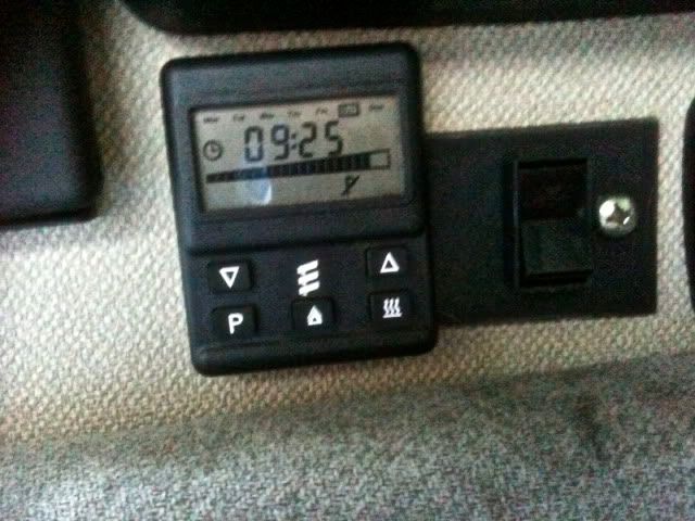
The 7 day timer that comes with it only lets it run for an hour before shutting it down. This has its plus points, before you get in bed let it run for an hour then have it come on every couple of hours just to keep the chill off, or have it come on i the morning to defrost the van etc. You can adjust the temperature on the digital screen on the bottom of the display with the up and down buttons.
If you want the heater to stay on all the time on low for example so it doesnt drain your leisure battery with a series of start ups and shut downs this is what I did,
The yellow wire on the timer is the switch wire for the ebber from the timer.
I put a 16A switch from a live to the yellow wire and mounted it to the right of the control unit on a blanking plate.
This way I flick the switch and it stays on as long as I like and I can adjust the temperature still via the control unit.
It took five minutes to do.
jed
Re: One last eber Q.........
Cheers chaps. Think that mobile thingy looks too hard for me- do you accept jiffy bags/$ in the post ?
Jed , I used to have one of those timers but ditched it in favour of an OE style one that fitted in the dash (on a T4). Yours is the better design as it has more variables and you can chnage on/off times over the 7 days.
Do you have a manual for it?
It IS adjustable for run time. From memory push and hold (erm , 99% sure its bottom right , the 'heat vapour' pic) you then use up and down buttons.
As default it is one hour but you can adjust cycle to run for only 30 mins up to a couple of hours or constant IIRC.
Re: One last eber Q.........
I was close(ish)
Check here Jed for how to adjust run time- first page.
http://www.eberspacher.com/downloads/te ... /SFX95.pdf
Check here Jed for how to adjust run time- first page.
http://www.eberspacher.com/downloads/te ... /SFX95.pdf
-
jed the spread
- Trader
- Posts: 9020
- Joined: 09 Oct 2005, 17:31
- 80-90 Mem No: 1967
- Location: Sutton in'it Syncronaut: 123
- Contact:
Re: One last eber Q.........
Nice one
jed
jed
-
lloydy

- Registered user
- Posts: 8048
- Joined: 24 Nov 2009, 17:54
- 80-90 Mem No: 5262
- Location: cheam surrey
Re: One last eber Q.........
Sooo can you fit these digistats onto the older ebers? Like the idea of time control. And jed, presume your eber is different to mine? as mine is in metal box fitted to the bottom of van. Liking the silencer as well. Just need one for the fuel pump ticktickticktickticktickticktickticktickticktickticktick
Time is a drug. Too much of it kills you
-
Oldiebut goodie
- Registered user
- Posts: 7528
- Joined: 18 Apr 2008, 01:19
- 80-90 Mem No: 11135
- Location: Eastern Angle
Re: One last eber Q.........
Jed,
your exhaust pipe should be a continuous downward slope - you will get a build up of condensation in that loop hanging down - you could drill a 1/16" hole at the lowest point to allow it to drain.
Manufacturers exhaust for use in a boat when the exhaust has to slope up:

your exhaust pipe should be a continuous downward slope - you will get a build up of condensation in that loop hanging down - you could drill a 1/16" hole at the lowest point to allow it to drain.
Manufacturers exhaust for use in a boat when the exhaust has to slope up:
1.6D 2019 VW T-Cross
200hp VW T6
1̶Y̶ ̶1̶9̶8̶7̶ ̶H̶i̶-̶t̶o̶p̶ ̶C̶a̶r̶a̶v̶e̶l̶l̶e̶
5̶0̶8̶d̶ ̶M̶e̶r̶c̶
200hp VW T6
1̶Y̶ ̶1̶9̶8̶7̶ ̶H̶i̶-̶t̶o̶p̶ ̶C̶a̶r̶a̶v̶e̶l̶l̶e̶
5̶0̶8̶d̶ ̶M̶e̶r̶c̶
-
v-lux
- Trader
- Posts: 737
- Joined: 07 Aug 2006, 18:54
- 80-90 Mem No: 2951
- Location: Somerset....yarp!
- Contact:
Re: One last eber Q.........
Is that what appears to be a bloody great hole cut in the floor of your van Jed?
Ive been doing quite a bit of thinking about where to install a heater on my van, but i really don't want to cut the floor if possible. Once upon a time my van had a heater of some kind (webasto i reckon) mounted in behind the right hand tail light, however i think it was a water heating type. The 'T' offs in the coolant pipes are still there, as is a fuel pipe going into the diesel tank and the metal (behind the battery tray) has holes cut in it for exhaust etc.
Do these airblown type heaters mind getting wet? Ive been wondering if i might be able to put an airblown type behind the battery and just have the ducting making its way into the van? Just figure that the heater unit itself is going to get a bit wet on occasion being right at the back there.
Other option is to re-install another water heating type heater, ive been toying with the idea of putting underfloor heating in to act like a radiator additional to the heater matrix being warmed up?

Re: One last eber Q.........
but i really don't want to cut the floor if possible.
Cut it Al, neatly, weld or rivet a matching doubler underneath, deburr, rust treat, paint and breath again.
I'm gonna, even though don't wanna (sounds like a title for a song coming on, wish i could sing )
The 80-90 Tech Wikipedia Your 1st port of call
Syncro Kastenwagen / 16" Kombi Camper
Syncronaut No. 1
-
v-lux
- Trader
- Posts: 737
- Joined: 07 Aug 2006, 18:54
- 80-90 Mem No: 2951
- Location: Somerset....yarp!
- Contact:
Re: One last eber Q.........
Cut it Al
Do you think? You reckon its better to cut the floor than mount it behind the rear light?
Does everyone mount it in the same place generally? What would be in the cupboard under the rock n roll seat? ( i know some people put them under the glovebox, but i'm not keen on that. No one got it in the engine bay somewhere? (I must admit to not knowing too much about the install of these things, there's probably a really obvious reason why not if youre familiar with them..?)
Re: One last eber Q.........
You have two option of mounting them when it comes to hole cutting
(1) drill the 4 holes for mounting bolts and then a further 3- inlet/outlet and fuel line , so all the pipes exit the floor with minimal of cutting
(2) Cut a larger sqaure and mount eber onto a plate.
eberspacher giver you the choice of either in the workshop book and supply gaskets/plates/seals to do both.
I went for option one this afternoon (inbetween rain storms) and would seriously consider #2 if doing it again. Drilling 7 holes tot he perfect size all perfectly spaced is a nightmare, even using mounting plate as template. (note- easiest way to do it is to copy the diagram perfectly onto paper then stick the paper onto the floor-giving you a perfect template without having to guess hole centres)
-
v-lux
- Trader
- Posts: 737
- Joined: 07 Aug 2006, 18:54
- 80-90 Mem No: 2951
- Location: Somerset....yarp!
- Contact:
Re: One last eber Q.........
So, is there a reason why it cant be mounted behind the tail light?
Just wondering as i can easily get the hot air ducting into the van by going up through next to the engine cover (ive got a slighty raised level bed and the ducting can travel underneath that)
Just wondering as i can easily get the hot air ducting into the van by going up through next to the engine cover (ive got a slighty raised level bed and the ducting can travel underneath that)