Sorry I took so long.
Please let me know if you spot any major errors.
But - as said before, different vehicles have their connections from the looms attached to different pins sharing the same internal connections.
CE1 Fuse box - Map of G Pins.
Moderators: User administrators, Moderators
-
Robsey

- Registered user
- Posts: 1197
- Joined: 19 May 2012, 20:45
- 80-90 Mem No: 11137
- Location: East Manchester
Re: CE1 Fuse box - Map of all Connector Pins.
Last edited by Robsey on 08 Jun 2021, 20:52, edited 1 time in total.
1983 Tin Top with a poorly DF and 4 speed DT box.
1987 Electrics and a DJ engine.
Maybe one day I might get it finished
1987 Electrics and a DJ engine.
Maybe one day I might get it finished
-
steveo9007

- Trader
- Posts: 319
- Joined: 21 May 2019, 17:49
- 80-90 Mem No: 16902
- Location: Cornwall
Re: CE1 Fuse box - Map of G Pins.
bloody hell, amazing stuff, this has got to be made into the wiki.. 
1985 RHD Pop Top Autosleeper, 1.7D KY Engine 4 Speed ALD Gearbox (Bertie)
-
Robsey
- Registered user
- Posts: 1197
- Joined: 19 May 2012, 20:45
- 80-90 Mem No: 11137
- Location: East Manchester
Re: CE1 Fuse box - Map of G Pins.
I would wait until we are sure that any major errors are corrected before even considering going down the wiki route.
1983 Tin Top with a poorly DF and 4 speed DT box.
1987 Electrics and a DJ engine.
Maybe one day I might get it finished
1987 Electrics and a DJ engine.
Maybe one day I might get it finished
-
syncroandy

- Trader
- Posts: 1857
- Joined: 18 Oct 2005, 18:15
- 80-90 Mem No: 851
- Location: North Lancs. UK
- Contact:
Re: CE1 Fuse box - Map of G Pins.
All I would suggest is if publishing any such info, make sure to state its origin, so that anyone using it can assess its relevance to their particular wiring, which as has already been said, does vary depending on factors such as country, equipment level etc.
Syncrosport
Volkswagen Transporter, reloaded.
252 GC5 EJ25 AAN L90D
246 097 AFN AVL+ L90D
Syncronaut #004
Volkswagen Transporter, reloaded.
252 GC5 EJ25 AAN L90D
246 097 AFN AVL+ L90D
Syncronaut #004
-
clift_d

- Registered user
- Posts: 3297
- Joined: 04 Oct 2012, 23:51
- 80-90 Mem No: 11695
- Location: Hackney innit
Re: CE1 Fuse box - Map of G Pins.
That's amazing - thanks for your work in pulling this together.
1988 LHD T25 1.6TD Westfalia Club Joker Hightop syncro
-
syncroandy
- Trader
- Posts: 1857
- Joined: 18 Oct 2005, 18:15
- 80-90 Mem No: 851
- Location: North Lancs. UK
- Contact:
Re: CE1 Fuse box - Map of G Pins.
For readibility a table layout works well, something like this (which has been up for at least a decade for anyone bothered to look at):
Central Electric 1 (a2resource.com)
Central Electric 1 (a2resource.com)
Syncrosport
Volkswagen Transporter, reloaded.
252 GC5 EJ25 AAN L90D
246 097 AFN AVL+ L90D
Syncronaut #004
Volkswagen Transporter, reloaded.
252 GC5 EJ25 AAN L90D
246 097 AFN AVL+ L90D
Syncronaut #004
-
Robsey
- Registered user
- Posts: 1197
- Joined: 19 May 2012, 20:45
- 80-90 Mem No: 11137
- Location: East Manchester
Re: CE1 Fuse box - Map of G Pins.
Ah yes...
I have seen that table too.
In fact I used that sort of thing to confirm how my own fusebox was laid out.
Hopefully different formats will help different people.
I have seen that table too.
In fact I used that sort of thing to confirm how my own fusebox was laid out.
Hopefully different formats will help different people.
1983 Tin Top with a poorly DF and 4 speed DT box.
1987 Electrics and a DJ engine.
Maybe one day I might get it finished
1987 Electrics and a DJ engine.
Maybe one day I might get it finished
-
Stesaw
- Registered user
- Posts: 1937
- Joined: 10 Aug 2019, 23:30
- 80-90 Mem No: 17004
- Location: Coventry
Re: CE1 Fuse box - Map of G Pins.
Robsey wrote: ↑08 Jun 2021, 20:06 There is no Plug 'F' and we started off with the G pins.
So next up -
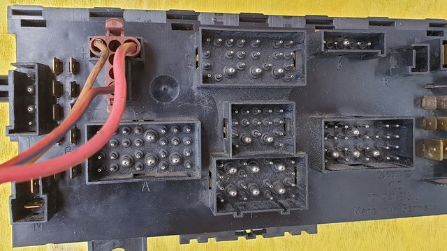
Connector H - Brown Plug.
H BROWN 2 STAGE RELAY FOR RAD FAN
H1 BROWN 2ND STAGE RELAY GROUND - RELAY 5 (J101) PIN 5 (85)
H2 INTERNAL red black - 2 STAGE RELAY (J101) RELAY PIN 2
H3 RED - CONNECTOR T3H / 1 - RAD FAN RELAY PIN 8 (87)
H4 INTERNAL green yellow - 2 STAGE RELAY (J101) RELAY PIN 7
H5 INTERNAL yellow red - 2 STAGE RELAY (J101) RELAY PIN 3
H6 RED / BLUE RADIATOR THERMO SWITCH PIN 1 RELAY PIN 6 (86)
This is just the post ive been looking for. Started on swapping my early fusebox today but found out I dont seem to have the H connector. The rad switch had a small strip fused relay that sits above the fusebox instead and I'm wondering where that connects. I'm also pondering depinning connections as some of the wires have been bodged.
1985 LeisureDrive 2.1DJ 5 Speed syncro conversion project.
1979 LT 2.0CH Westy project
1979 LT 2.0CH Westy project
-
Robsey
- Registered user
- Posts: 1197
- Joined: 19 May 2012, 20:45
- 80-90 Mem No: 11137
- Location: East Manchester
Re: CE1 Fuse box - Map of G Pins.
To be honest, unless you plan to fit air-con, you would not need this connector.
It is only for the second stage cooling fan relay.
I have put this in my van, so that I can have a bypass switch. (Chicken switch).
The air-con equipped system normally uses a three pin thermo switch in the radiator...
2 - Standard temperature = 92°C,
1 - Higher temperature = 102°C
3 - Fused supply.
The "standard" non-air-con vans have the normal two pin switch -
1 - Standard temperature = 92°C,
2 - Fused supply.
So - without the higher threshold switch, it will never trigger the relay.
Same if you only have a single speed (two pin) cooling fan motor.
As for the other wires...
Here is my over-ride switch wiring diagram.
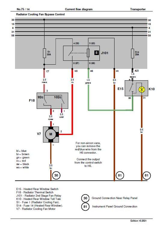
If you are wiring per factory, then the wire that goes from the 102°C contact is wired to the connector pin H6.
(Ignore my switch).
It is only for the second stage cooling fan relay.
I have put this in my van, so that I can have a bypass switch. (Chicken switch).
The air-con equipped system normally uses a three pin thermo switch in the radiator...
2 - Standard temperature = 92°C,
1 - Higher temperature = 102°C
3 - Fused supply.
The "standard" non-air-con vans have the normal two pin switch -
1 - Standard temperature = 92°C,
2 - Fused supply.
So - without the higher threshold switch, it will never trigger the relay.
Same if you only have a single speed (two pin) cooling fan motor.
As for the other wires...
Here is my over-ride switch wiring diagram.
If you are wiring per factory, then the wire that goes from the 102°C contact is wired to the connector pin H6.
(Ignore my switch).
1983 Tin Top with a poorly DF and 4 speed DT box.
1987 Electrics and a DJ engine.
Maybe one day I might get it finished
1987 Electrics and a DJ engine.
Maybe one day I might get it finished
-
Robsey
- Registered user
- Posts: 1197
- Joined: 19 May 2012, 20:45
- 80-90 Mem No: 11137
- Location: East Manchester
Re: CE1 Fuse box - Map of G Pins.
I suspect that your relay is a retro-fit item as the only supplementary fuses are blade fuses in relay positions 15 and 16 - although this appears to be only for 1986 and 1987 vans.
UPDATE - Incorrect... there may be various model specific options fitted to the van, each of which would require a supplementary fuse location.
For info, these fuses are:-
S27 (relay 15) 10 amps
Rear Fog Light
1mm grey/white
From Fog Light switch (E23) Terminal 83b to rear fog loom.
Connector T1h - fuse connection,
Then T1n - Engine bay junction box connector,
Then Rear Fog light (L20).
S50 (relay 16) 10 amps
Dimmed Illumination.
0.5mm grey/blue
From light switch dimmer control (E20) on light switch assembly (E1) - Terminal 58b.
To all dimmed circuits and Fusebox A1.
UPDATE:-
As we are all learning. I failed to realise that the second stage relay is not just an air-con thing.
I understand that Turbo Diesels may have a three pin temperature switch in the radiator.
And either a two-pin of three pin radiator fan.
Lower temperature threshold switch output wire goes to the radiator fan via a ceramic resistor behind the left headlight assembly, for a low speed fan output.
And the higher temperature switch threshold wire gives full fan speed via the relay.
1983 Tin Top with a poorly DF and 4 speed DT box.
1987 Electrics and a DJ engine.
Maybe one day I might get it finished
1987 Electrics and a DJ engine.
Maybe one day I might get it finished
-
Stesaw
- Registered user
- Posts: 1937
- Joined: 10 Aug 2019, 23:30
- 80-90 Mem No: 17004
- Location: Coventry
Re: CE1 Fuse box - Map of G Pins.
Well before I retrofitted the late fusebox I was using the early torpedo type fusebox as my van is a 1985, but its a mix of early and late.
There was the relay 43 (if I recall) And the load reduction relay (forget the number) as well tied into eachother above the fusebox on the A pillar.
The syncro i broke for conversion which was diesel and a 1987 had just the one relay which was higher amp assuming because its a single stage fan thats got more oomph. There were only two wires into the diesel fan whereas the petrol fan has the three for the two stage.
1985 LeisureDrive 2.1DJ 5 Speed syncro conversion project.
1979 LT 2.0CH Westy project
1979 LT 2.0CH Westy project
-
Robsey
- Registered user
- Posts: 1197
- Joined: 19 May 2012, 20:45
- 80-90 Mem No: 11137
- Location: East Manchester
Re: CE1 Fuse box - Map of G Pins.
The indicator / hazard light flasher relay and load reduction relay are on the top of the torpedo-fuse fusebox, and the coolant shortage module (42 or 43 relay) is mounted up on the A pillar near the earth crowns.
See here for the Torpedo Box thread... here.
viewtopic.php?t=177047
See here for the Torpedo Box thread... here.
viewtopic.php?t=177047
1983 Tin Top with a poorly DF and 4 speed DT box.
1987 Electrics and a DJ engine.
Maybe one day I might get it finished
1987 Electrics and a DJ engine.
Maybe one day I might get it finished
-
Stesaw
- Registered user
- Posts: 1937
- Joined: 10 Aug 2019, 23:30
- 80-90 Mem No: 17004
- Location: Coventry
Re: CE1 Fuse box - Map of G Pins.
Yeah thats right. Still trying to source the H connector for the ce fusebox
1985 LeisureDrive 2.1DJ 5 Speed syncro conversion project.
1979 LT 2.0CH Westy project
1979 LT 2.0CH Westy project
-
Robsey
- Registered user
- Posts: 1197
- Joined: 19 May 2012, 20:45
- 80-90 Mem No: 11137
- Location: East Manchester
Re: CE1 Fuse box - Map of G Pins.
H Connector?
This one - for two stage fan?
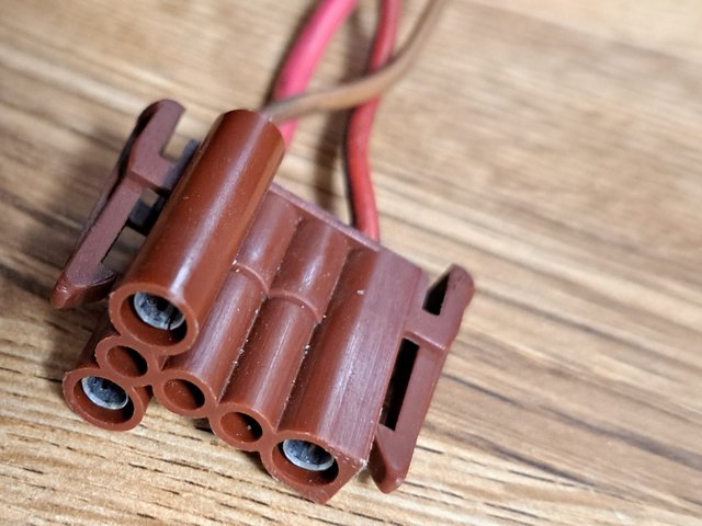

pm on it's way.
Hmm - it is amazing what you find when looking for a totally unrelated piece of cabling...
In this case, I was looking for a mini inhibit loom for a powered wheelchair for a patient of mine.
She keeps turning her chair on accidentally when driving her adapted van.....
This one - for two stage fan?
pm on it's way.
Hmm - it is amazing what you find when looking for a totally unrelated piece of cabling...
In this case, I was looking for a mini inhibit loom for a powered wheelchair for a patient of mine.
She keeps turning her chair on accidentally when driving her adapted van.....
1983 Tin Top with a poorly DF and 4 speed DT box.
1987 Electrics and a DJ engine.
Maybe one day I might get it finished
1987 Electrics and a DJ engine.
Maybe one day I might get it finished

Re: CE1 Fuse box - Map of G Pins.
Well done, Robsey. Invaluble work to share.
Certainly helps fitting up my cruise control.
Certainly helps fitting up my cruise control.
MaxStu
1989 DJ 2.1 Auto Leisuredrive rusty bucket.
1987 DG1.9 LPG Auto Autosleeper
"Blissfully happy in your presence".
1989 DJ 2.1 Auto Leisuredrive rusty bucket.
1987 DG1.9 LPG Auto Autosleeper
"Blissfully happy in your presence".