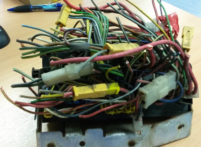
As part of my conversion from early fuse box to the later CE1 fuse box, I mapped out every single pin in the fusebox.

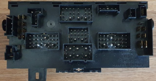
I found that the pins in the "G" connector cluster are not used as much as they could be.
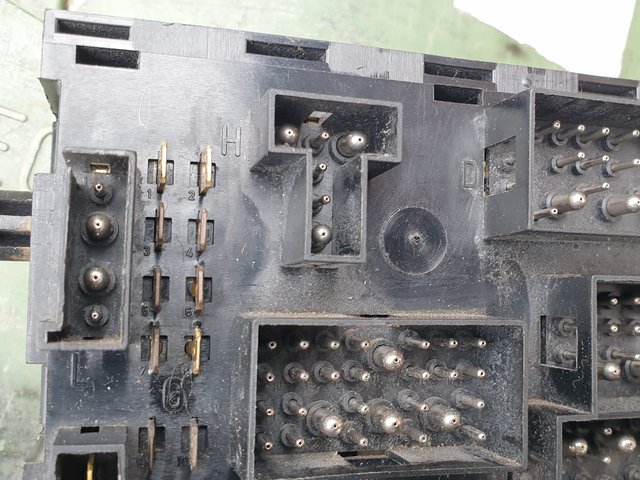
They are numbered G1 to G10, starting top left and finishing bottom right.
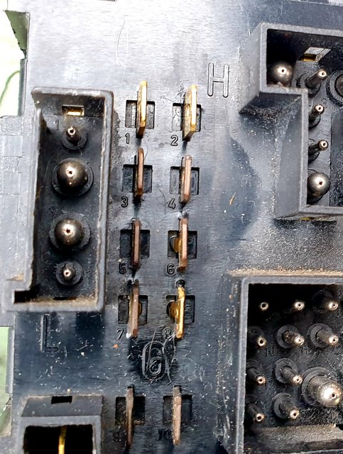
So - here is what I found.
Pin G1 (top left)
X-Contact (12v when running).
Black / Yellow wire for rear warm air blower if fitted.
Internal connections to:-
E8 - Black / Grey to rear wiper motor pin 53a
G3 - see below.
Output from fuse S12 -20 amps.
Relay 11 - pin 3 (53a)
Pin G2 (top right)
Ignition live -
Optional Black wire to Cruise control where fitted.
Internal connections to:-
A25 - Black wire to brake warning indication light.
D7
G5 - see below.
Output from Fuse S18 - normally 10amps, but uprated to 15amps where cruise control is fitted.
Pin G3
X-Contact (12v when running).
Normally signified by Black / Yellow wires.
Internal connections to:-
G1 - see above
E8 - Black / Grey to rear wiper motor pin 53a
Output from fuse S12 -20 amps.
Relay 11 - pin 3 (53a)
G4
Alternator Charge Light Signal.(61 rail).
Blue wire to auxilliary battery cut-out relay pin 86 where fitted.
Internal connections to:-
A16 - sometimes wired instead of E13, or wired to B1.
B1 - Blue wire to charge light in instrument cluster
C2.
D4
E13 - Blue wire to alternator pin D+
Pin G5.
Ignition live supply
Internal connections to:-
A25 - Black wire to brake warning indication light.
D7
G2 - see above.
Output from Fuse S18 -10 amps.
Pin G6
No specific function.
Internal links only to pins:-
A4
D1
Pin G7
56 Voltage rail. (Feed to head lamp circuit).
Internal connections to:-
A9 - White / Black wire from light switch pin 56, and also to the dip / high beam stalk pin 56.
M1 - not used.
G8
Dimming illumination.
Internally connected to:-
A1 - Grey / Blue wire for all dash switches and output from light switch rheostat).
G9
Non-dimming Illumination.
Internally connected to -
A26 - Grey wire to lighting rheostat pin 58e.
E1 - Grey / Green wire to rear number plate lights,
And fuse S20.
G10
X-Contact (12v when running).
Internal connections to
A19 - Green / Red to wash / wipe stalk switch pin T
C9 - Green / Red to front washer pump.
D5.
I hope it helps.
It has allowed me to wire in a few extras without having to chop into wires.