Digital Clock Current Flow Diagram
Posted: 27 Jan 2014, 10:25
Hi
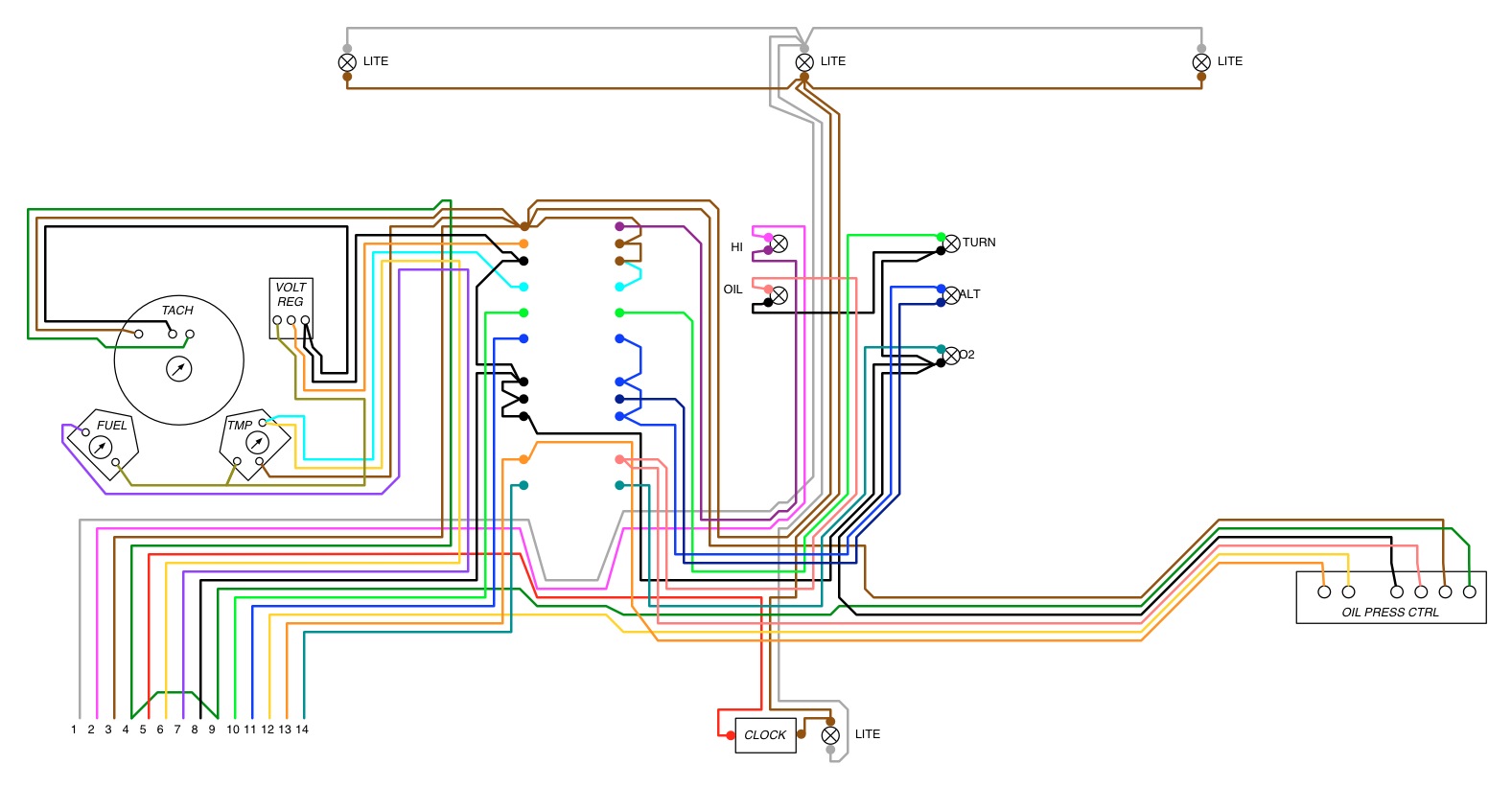
I have now fitted a new digital clock to the existing aperture on the instrument cluster, however when i went and restored the instrument cluster in to the dash and power it up I am not getting any voltage at the plug socket where the existing digital clock plugged into the instrument cluster PCB via the white 2 pin plug,
So the first question is
1. What is the voltage of the digital clock which was originally fitted??
2. Does any one have a wiring diagram/ current flow diagram for the digital clock.
3. Is an English translastion of the PCB tracks identification available - Where the instrument cluster plugs into the wiring loom the PCB tracks in the socket have labels but they are in German.
This would be a great help to enable me to trace it though from the +ve supply, through some components to the clock white plug and back to -ve
Thanks Dave