What would a diode on the voltage regulator relay do exactly? Would it just light up to show that it's getting power?
Dashboard PCB Replacement (CJH Design)
Moderators: User administrators, Moderators
-
The Hairy Camper
- Registered user
- Posts: 385
- Joined: 03 May 2017, 00:19
- 80-90 Mem No: 16820
- Location: Cheshire
Re: Dashboard PCB Replacement (CJH Design)
Thanks TT, that looks impressive, but could be a map to the nearest loo in work for all I know 
What would a diode on the voltage regulator relay do exactly? Would it just light up to show that it's getting power?
What would a diode on the voltage regulator relay do exactly? Would it just light up to show that it's getting power?
1984 Autosleeper, pop-top, 1.9 1Y, 5-Speed
-
TwinTurbo
- Registered user
- Posts: 360
- Joined: 04 Sep 2024, 03:49
- 80-90 Mem No: 17758
- Location: carlisle
Re: Dashboard PCB Replacement (CJH Design)
It's not a LED Diode but a regular no light emitting one ( although it would work )
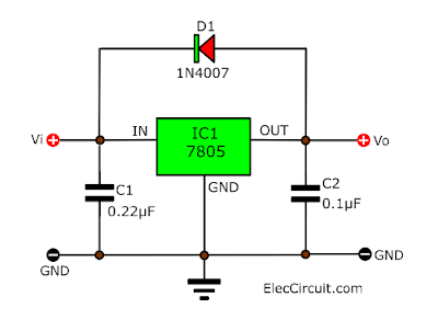
D1 in the diagram is there to protect the voltage regulator internal circuitry. if you imagine capacitor C2 is storing 5V all the time the circuit is on, then when the input is turnd off there is a chance the currenct will flow back into the 7805 to ground and damage the chip ( unlikely but hey what's best practice for ) insteed it would flow through D1 and ground via C1.
Never killed one without a diode but for a few pennies of components save having a failure.
TwinTurbo
1985 1.9 DG Caravelle Autohomes Karisma
1985 1.9 DG Caravelle Autohomes Karisma
-
icosahedron

- Registered user
- Posts: 60
- Joined: 12 Aug 2010, 21:12
- 80-90 Mem No: 8620
- Location: UK
Re: Dashboard PCB Replacement (CJH Design)
D1 provides regulator input short circuit protection. It is only required if a high-value capacitor (hundreds of uF) is connected to the output in parallel with C2. In case of a regulator input short circuit, the high-value capacitor is discharged via D1 instead of through the regulator with the current reversed, which may damage it. Under normal operation the load on the regulator discharges the capacitor when input power is removed.
Capacitors in combination with the regulator will have no effect on the bimetal gauges; there is nothing wrong with the design as is without capacitors and diode.
Capacitors in combination with the regulator will have no effect on the bimetal gauges; there is nothing wrong with the design as is without capacitors and diode.
Re: Dashboard PCB Replacement (CJH Design)
 I took this screenshot back in 2021 as this member appears to have been able to get some of C j h ‘s designs made ( he used his user name printed on the board)
 Is this member still active on the club and maybe he might be able to help.

-
The Hairy Camper
- Registered user
- Posts: 385
- Joined: 03 May 2017, 00:19
- 80-90 Mem No: 16820
- Location: Cheshire
Re: Dashboard PCB Replacement (CJH Design)
Excellent find, Cecil. Thank you for sharing.
I will try and message him.
It looks as though it's not too difficult to replicate these boards if you know what you're doing. I believe Twin Turbo may have cracked it (and improved it) with his schematics too.
The actual dimensions are the next thing I believe I need to sort out.
I will try and message him.
It looks as though it's not too difficult to replicate these boards if you know what you're doing. I believe Twin Turbo may have cracked it (and improved it) with his schematics too.
The actual dimensions are the next thing I believe I need to sort out.
1984 Autosleeper, pop-top, 1.9 1Y, 5-Speed
-
TwinTurbo
- Registered user
- Posts: 360
- Joined: 04 Sep 2024, 03:49
- 80-90 Mem No: 17758
- Location: carlisle
Re: Dashboard PCB Replacement (CJH Design)
If he has the eagle files then that makes it a shed ton easier.
Dimensions wise , the main thing is the spacing of the 4 mounting holes and 6 LED's nothing else maters on the main board. I
If anyone has a edge conector plug going spare that would help for doing the adapter board.
I am not sure why the original design does not have fixed configuration on the adapter baord and selecteable configurations with jumpers on the PCB.
TwinTurbo
1985 1.9 DG Caravelle Autohomes Karisma
1985 1.9 DG Caravelle Autohomes Karisma
-
The Hairy Camper
- Registered user
- Posts: 385
- Joined: 03 May 2017, 00:19
- 80-90 Mem No: 16820
- Location: Cheshire
Re: Dashboard PCB Replacement (CJH Design)
Ianders profile says he hasen't been on club8090 for over a year now. I've sent a message this morning, but he also could have left the forum now.
I believe there are only 2 mounting holes on CJH's board. If we can line those up (with one of CJH's pictures), I assume everything else should line up?
I took some pictures/measurements of my dash the other day. Anyone on here good enough to photoshop things so we can get an idea of the dimensions?
1984 Autosleeper, pop-top, 1.9 1Y, 5-Speed
-
The Hairy Camper
- Registered user
- Posts: 385
- Joined: 03 May 2017, 00:19
- 80-90 Mem No: 16820
- Location: Cheshire
Re: Dashboard PCB Replacement (CJH Design)
These are the best pictures of CJH's board that I can find.
Can anybody use them?


Can anybody use them?
1984 Autosleeper, pop-top, 1.9 1Y, 5-Speed
-
icosahedron
- Registered user
- Posts: 60
- Joined: 12 Aug 2010, 21:12
- 80-90 Mem No: 8620
- Location: UK
Re: Dashboard PCB Replacement (CJH Design)
There you go, 10 pixels = 1/10".
-
The Hairy Camper
- Registered user
- Posts: 385
- Joined: 03 May 2017, 00:19
- 80-90 Mem No: 16820
- Location: Cheshire
Re: Dashboard PCB Replacement (CJH Design)
Can you give me that in millimetres for both PCB's?
1984 Autosleeper, pop-top, 1.9 1Y, 5-Speed
-
TwinTurbo
- Registered user
- Posts: 360
- Joined: 04 Sep 2024, 03:49
- 80-90 Mem No: 17758
- Location: carlisle
Re: Dashboard PCB Replacement (CJH Design)
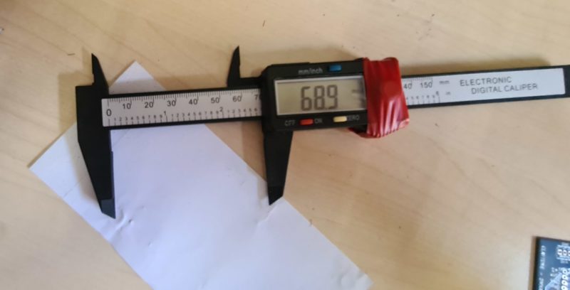
I did a rubbing of the moutning holes on a peice of paper and them measured the distances from the edge to each mounting hole, did the maths and foudn the distance they are appart.
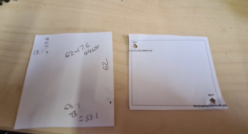
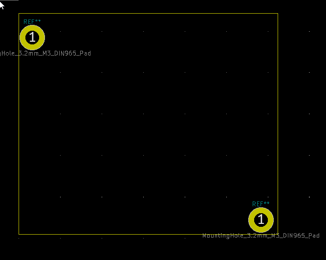
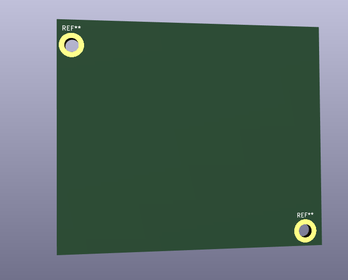
Then nocked up a very quick board outline in KiCard , put on two mounding holes 3.2mm ( may have to change that but easy job )
Printed it on paper and checked the alignment which looked fairly good.
This is the board layout view.
This is the 3D render.
If my main D printer is working ( I can't remember if I fixed it after it last broke ) I may nock up a Model in onshape and print it to check fit. my other 3D printer has been in bits for months.
TwinTurbo
1985 1.9 DG Caravelle Autohomes Karisma
1985 1.9 DG Caravelle Autohomes Karisma
-
TwinTurbo
- Registered user
- Posts: 360
- Joined: 04 Sep 2024, 03:49
- 80-90 Mem No: 17758
- Location: carlisle
Re: Dashboard PCB Replacement (CJH Design)
Been busy today though ...
Fitted a wheel cylinder to my Robin Hood Kit car, Changed the Cam belt and water pump and attempted to fit the pipes on my juicy new fat core alloy rad...
Then fixed one project for my son. there had been some software issus and I came across a bug as the number of steps on the stepper motor exceeded the value that could be stored by the type of variable being used. Easily fixed once I had realised my error.
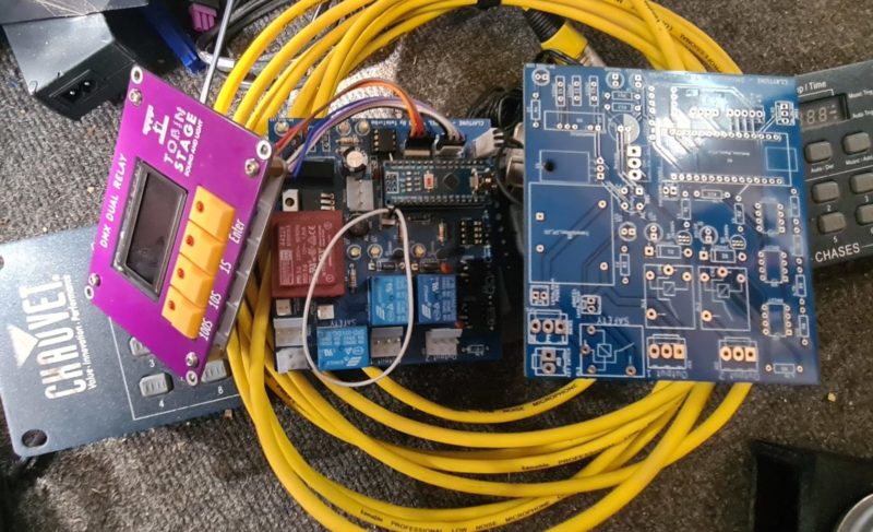
DMX controlled stepper motor board and he built the pully reduction rig.
And then fixed another project for my son that I have been working on for 4 years. Kind of kept falling by the wayside.. He just needs to put it in a nice encloseure with hardware.
And DMX controled mains relay switching board.
Fitted a wheel cylinder to my Robin Hood Kit car, Changed the Cam belt and water pump and attempted to fit the pipes on my juicy new fat core alloy rad...
Then fixed one project for my son. there had been some software issus and I came across a bug as the number of steps on the stepper motor exceeded the value that could be stored by the type of variable being used. Easily fixed once I had realised my error.
DMX controlled stepper motor board and he built the pully reduction rig.
And then fixed another project for my son that I have been working on for 4 years. Kind of kept falling by the wayside.. He just needs to put it in a nice encloseure with hardware.
And DMX controled mains relay switching board.
TwinTurbo
1985 1.9 DG Caravelle Autohomes Karisma
1985 1.9 DG Caravelle Autohomes Karisma
-
The Hairy Camper
- Registered user
- Posts: 385
- Joined: 03 May 2017, 00:19
- 80-90 Mem No: 16820
- Location: Cheshire
Re: Dashboard PCB Replacement (CJH Design)
Thanks for keeping this updated, TT. I started watching a video on how to use Kicad earlier today, but I'd be lucky if I figured out how these things work by Christmas.
If I can help in any other way, please let me know. I don't mind taking my dash apart again if you need any more measurements
When CJH made his paper mock up, I believe his measurements were 72.9mm x 126.4mm for the main PCB. Maybe this could help?

If I can help in any other way, please let me know. I don't mind taking my dash apart again if you need any more measurements

When CJH made his paper mock up, I believe his measurements were 72.9mm x 126.4mm for the main PCB. Maybe this could help?
Last edited by The Hairy Camper on 21 Jun 2025, 18:53, edited 1 time in total.
1984 Autosleeper, pop-top, 1.9 1Y, 5-Speed
-
icosahedron
- Registered user
- Posts: 60
- Joined: 12 Aug 2010, 21:12
- 80-90 Mem No: 8620
- Location: UK
Re: Dashboard PCB Replacement (CJH Design)
I made a mistake there; 25 pixels = 1/10" or 2.54 mm. That gives board sizes of 65 x 123 mm and 65 x 24 mm. I'll recheck it tonight to make sure I didn't mess up again.
Update:
My measurement of the distance between the two holes from the board image comes to 70 mm compared to TwinTurbo's 68.9 mm. Hole diameter = 3.5 mm.
-
The Hairy Camper
- Registered user
- Posts: 385
- Joined: 03 May 2017, 00:19
- 80-90 Mem No: 16820
- Location: Cheshire
Re: Dashboard PCB Replacement (CJH Design)
icosahedron wrote: ↑Yesterday, 17:30
I made a mistake there; 25 pixels = 1/10" or 2.54 mm. That gives board sizes of 65 x 123 mm and 65 x 24 mm. I'll recheck it tonight to make sure I didn't mess up again.
Update:
My measurement of the distance between the two holes from the board image comes to 70 mm compared to TwinTurbo's 68.9 mm
1mm difference sounds acceptable. What measurements do you get for length and width?
1984 Autosleeper, pop-top, 1.9 1Y, 5-Speed