What would a diode on the voltage regulator relay do exactly? Would it just light up to show that it's getting power?
Dashboard PCB Replacement (CJH Design)
Moderators: User administrators, Moderators
-
The Hairy Camper
- Registered user
- Posts: 381
- Joined: 03 May 2017, 00:19
- 80-90 Mem No: 16820
- Location: Cheshire
Re: Dashboard PCB Replacement (CJH Design)
Thanks TT, that looks impressive, but could be a map to the nearest loo in work for all I know 
What would a diode on the voltage regulator relay do exactly? Would it just light up to show that it's getting power?
What would a diode on the voltage regulator relay do exactly? Would it just light up to show that it's getting power?
1984 Autosleeper, pop-top, 1.9 1Y, 5-Speed
-
TwinTurbo
- Registered user
- Posts: 356
- Joined: 04 Sep 2024, 03:49
- 80-90 Mem No: 17758
- Location: carlisle
Re: Dashboard PCB Replacement (CJH Design)
It's not a LED Diode but a regular no light emitting one ( although it would work )
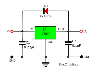
D1 in the diagram is there to protect the voltage regulator internal circuitry. if you imagine capacitor C2 is storing 5V all the time the circuit is on, then when the input is turnd off there is a chance the currenct will flow back into the 7805 to ground and damage the chip ( unlikely but hey what's best practice for ) insteed it would flow through D1 and ground via C1.
Never killed one without a diode but for a few pennies of components save having a failure.
TwinTurbo
1985 1.9 DG Caravelle Autohomes Karisma
1985 1.9 DG Caravelle Autohomes Karisma
-
icosahedron

- Registered user
- Posts: 57
- Joined: 12 Aug 2010, 21:12
- 80-90 Mem No: 8620
- Location: UK
Re: Dashboard PCB Replacement (CJH Design)
D1 provides regulator input short circuit protection. It is only required if a high-value capacitor (hundreds of uF) is connected to the output in parallel with C2. In case of a regulator input short circuit, the high-value capacitor is discharged via D1 instead of through the regulator with the current reversed, which may damage it. Under normal operation the load on the regulator discharges the capacitor when input power is removed.
Capacitors in combination with the regulator will have no effect on the bimetal gauges; there is nothing wrong with the design as is without capacitors and diode.
Capacitors in combination with the regulator will have no effect on the bimetal gauges; there is nothing wrong with the design as is without capacitors and diode.
Re: Dashboard PCB Replacement (CJH Design)
 I took this screenshot back in 2021 as this member appears to have been able to get some of C j h ‘s designs made ( he used his user name printed on the board)
 Is this member still active on the club and maybe he might be able to help.

-
The Hairy Camper
- Registered user
- Posts: 381
- Joined: 03 May 2017, 00:19
- 80-90 Mem No: 16820
- Location: Cheshire
Re: Dashboard PCB Replacement (CJH Design)
Excellent find, Cecil. Thank you for sharing.
I will try and message him.
It looks as though it's not too difficult to replicate these boards if you know what you're doing. I believe Twin Turbo may have cracked it (and improved it) with his schematics too.
The actual dimensions are the next thing I believe I need to sort out.
I will try and message him.
It looks as though it's not too difficult to replicate these boards if you know what you're doing. I believe Twin Turbo may have cracked it (and improved it) with his schematics too.
The actual dimensions are the next thing I believe I need to sort out.
1984 Autosleeper, pop-top, 1.9 1Y, 5-Speed
-
TwinTurbo
- Registered user
- Posts: 356
- Joined: 04 Sep 2024, 03:49
- 80-90 Mem No: 17758
- Location: carlisle
Re: Dashboard PCB Replacement (CJH Design)
If he has the eagle files then that makes it a shed ton easier.
Dimensions wise , the main thing is the spacing of the 4 mounting holes and 6 LED's nothing else maters on the main board. I
If anyone has a edge conector plug going spare that would help for doing the adapter board.
I am not sure why the original design does not have fixed configuration on the adapter baord and selecteable configurations with jumpers on the PCB.
TwinTurbo
1985 1.9 DG Caravelle Autohomes Karisma
1985 1.9 DG Caravelle Autohomes Karisma
-
The Hairy Camper
- Registered user
- Posts: 381
- Joined: 03 May 2017, 00:19
- 80-90 Mem No: 16820
- Location: Cheshire
Re: Dashboard PCB Replacement (CJH Design)
Ianders profile says he hasen't been on club8090 for over a year now. I've sent a message this morning, but he also could have left the forum now.
I believe there are only 2 mounting holes on CJH's board. If we can line those up (with one of CJH's pictures), I assume everything else should line up?
I took some pictures/measurements of my dash the other day. Anyone on here good enough to photoshop things so we can get an idea of the dimensions?
1984 Autosleeper, pop-top, 1.9 1Y, 5-Speed
-
The Hairy Camper
- Registered user
- Posts: 381
- Joined: 03 May 2017, 00:19
- 80-90 Mem No: 16820
- Location: Cheshire
Re: Dashboard PCB Replacement (CJH Design)
These are the best pictures of CJH's board that I can find.
Can anybody use them?


Can anybody use them?
1984 Autosleeper, pop-top, 1.9 1Y, 5-Speed
-
icosahedron
- Registered user
- Posts: 57
- Joined: 12 Aug 2010, 21:12
- 80-90 Mem No: 8620
- Location: UK
Re: Dashboard PCB Replacement (CJH Design)
There you go, 10 pixels = 1/10".
-
The Hairy Camper
- Registered user
- Posts: 381
- Joined: 03 May 2017, 00:19
- 80-90 Mem No: 16820
- Location: Cheshire
Re: Dashboard PCB Replacement (CJH Design)
Can you give me that in millimetres for both PCB's?
1984 Autosleeper, pop-top, 1.9 1Y, 5-Speed