VW Electrics rewiring Dashboard multipin connector
Original thread [1]
Covkid
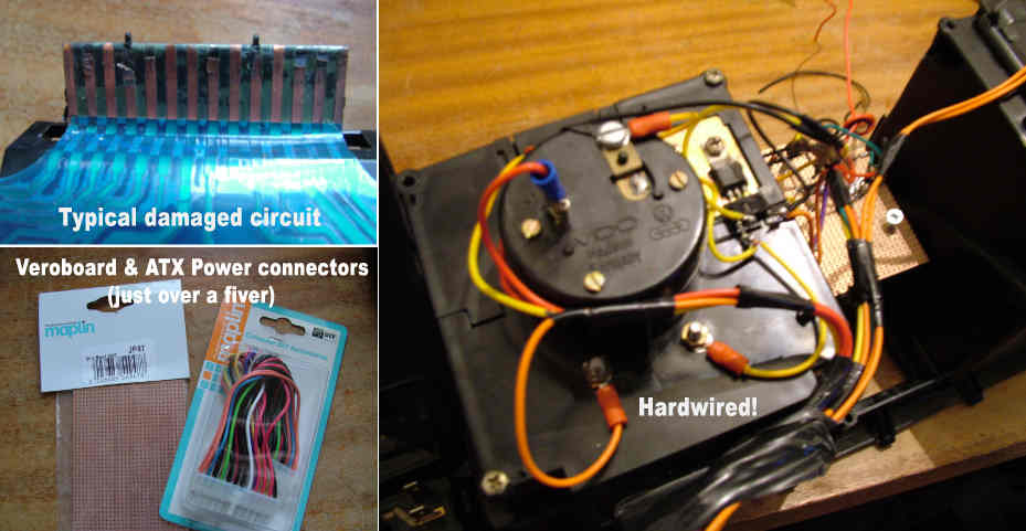
Got so cheesed off with that pathetic circuit board on the back of the clocks, I hardwired the whole thing today. Replaced the original connector olug with an ATX plug and socket from Maplins for £2.99 - normally used on computer motherboards for power supply connector. That then gave me way more possible routes in and out of clocks if I wanted to mount extra switches or whatever.
Chopped up an old computer power supply to give me all the linking cables I might need. cut the veroboard to size, made mounting holes and lined up LEDs on veroboard to match original then soldered everything up using original circuit as a guide. Reused all the resistors and diodes.
Hey presto no more intewrmittent lights and guages. Result!
Parts came to under a tenner including a box of crimp terminals (yes £1 shop no less) - veroboard and plug/socket came from Maplins.
Oh yes, added PCB sockets to veroboard to make LED replacement simple and added in an extra LED for future use.
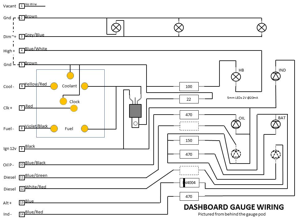
Well, it does pay if you can read a circuit diagram but basically you're replicating whats on the old one but in hardwired form. Gets a bit confusing in places but if you do one track at a time its not too bad. I've just reached the end of my tether with the old one and would rather have something I know won't break down on me any more. A sensible long-term solution might be an in-house printed circuit to do this job that any member can download, etch, drill and start assembling but I just went for veroboard as I wanted the job done. If I get more time I'll try to design a board to do this job but I'd need to look at all the T25s to make sure I'm covering everything like flyleads for a rev counter, glowplug light etc etc.
Definitely not a beginners project unless you have a spare dash and are in no hurry. Took me around 6 hours from beginning to end. A purpose-made board would have cut that down to an hour possibly. Ideally, a circuit board to take the place of existing plug would be good too - less messing about.
To get my veroboard to fit in the space behind the LEDs, I first cut it to fit (fairly tightly) then scraped four areas clear of copper and made holes big enough in those areas to screw into the four holes originally meant for that plastic sheild thing. Basically you need to start cutting a piece of veroboard and making those screw holes. You also have to ensure that a row of veroboard holes lines up with the original led holders on the flimsy crappy thing you have on there now, That way when you fit the LEDs to the veroboard, they'll line up. I started there then worked on one circuit at a time. Easier to do than explain really, but that was the basis - following each line from the multiplug and making a note of what it is for later connecting. Theres a diagram in the WIKI for the plug I think. The regulator/tranny that is currectly screwed to the back of the right hand clock can stay where it is. Could go on the veroboard but would imagine it'll need a heatsink then. I found it easier to leave it where it was to be honest.
Update: Theres a fairly comprehensive overview of the job over on the Samba: http://www.thesamba.com/vw/forum/viewtopic.php?t=573133&postdays=0&postorder=asc&start=0
More on hardwiring the dash
Midflife Crisis expanded this with some very useful plans. MANY thanks for this:
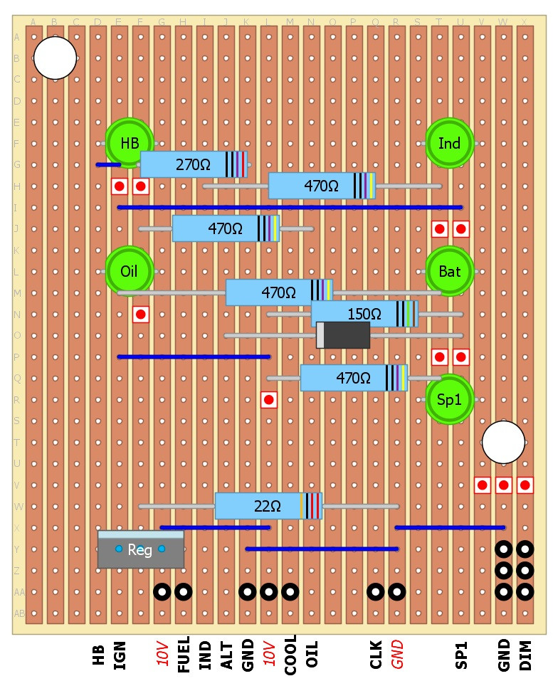
I thought the PCB layout that I used might be of use/interest to others.
Note that my dash is the simplest version out there - petrol, no rev counter, no clock (although I did include the clock wiring). I also added an additional light into the dash as a spare for the future.
Just to clarify this is a view from the component (top) side of the veroboard (even though you can see the vertical tracks that would be on the underside - imagine that the board is slightly transparent). The LED were mounted on the back of the Veroboard (i.e. on the track side, facing downwards). Each wire from the connector arrives at the board on the bottom row (shown by the wire names on the pic) The wires to the fuel gauge/coolant temp etc then come off the board on wires from the small black circles on the second from bottom row) The wires to the three illumination lights come off the board on the 6 x black circles on the bottom right of the board. The red dots are where the tracks are cut. Note that I used an LED for the High Beam so that has a different resistor value to the original circuit.
SP1 is my spare LED that is lit when the SP1 wire is grounded - just got to think of a use for this now.
For others trying this, the most useful information on here is probably the spacing of the mounting holes and the LEDS. (Note for reference that the component holes on the veroboard are 0.1" apart) You can design the board however you like but those elements need to be spaced as shown so that they will all mount correctly into the dash. Also its worth mentioning that the components are mounted so that they do not interfere with the various bits that stick up from the LED mounting section of the dash.
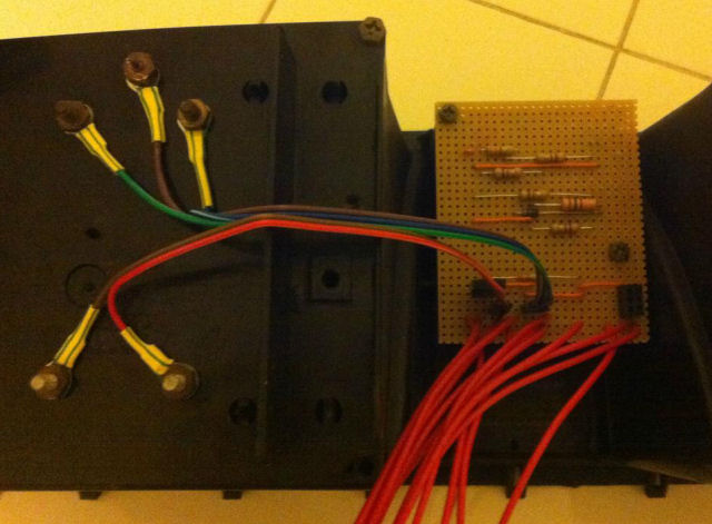
This is how it looks in the end;
(Note that the illumination lights are not connected in this pic - but the connectors can be seen on the bottom right of the board)
It seems to work really well - just need to do something about the blinding brightness of the blue LED for the High Beam.
AngeloEVS
Original thread http://forum.club8090.co.uk/viewtopic.php?f=11&t=49592
Ghost123uk added = more info and some great diagrams by MidLifeCrisis here = http://forum.club8090.co.uk/viewtopic.php?f=39&t=125921&p=7948161#p7948046


