Diesel engine wiring
Diesel Engine wiring
Black Box in engine bay
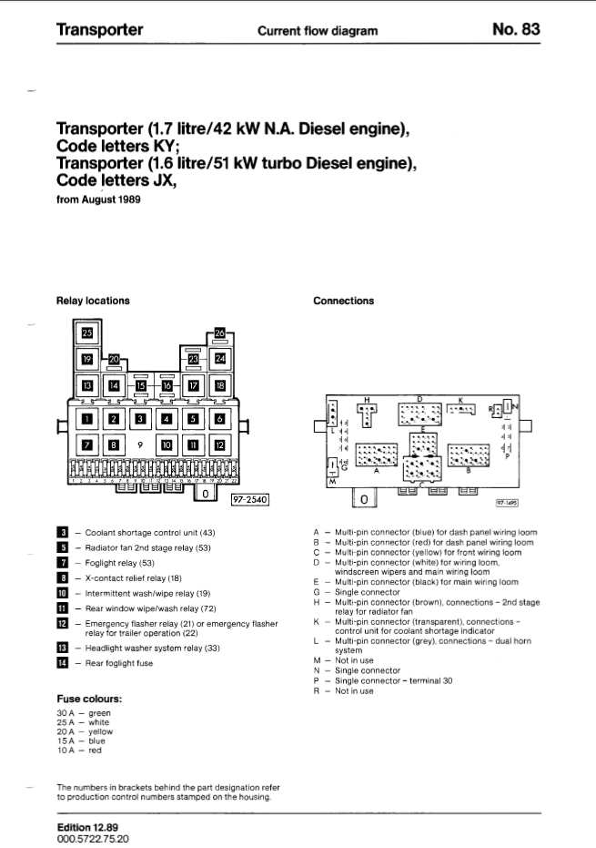
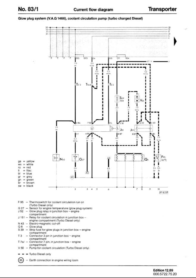
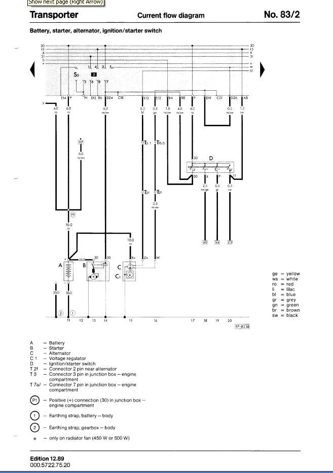
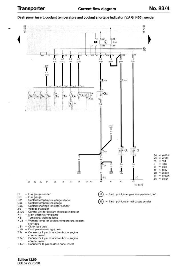
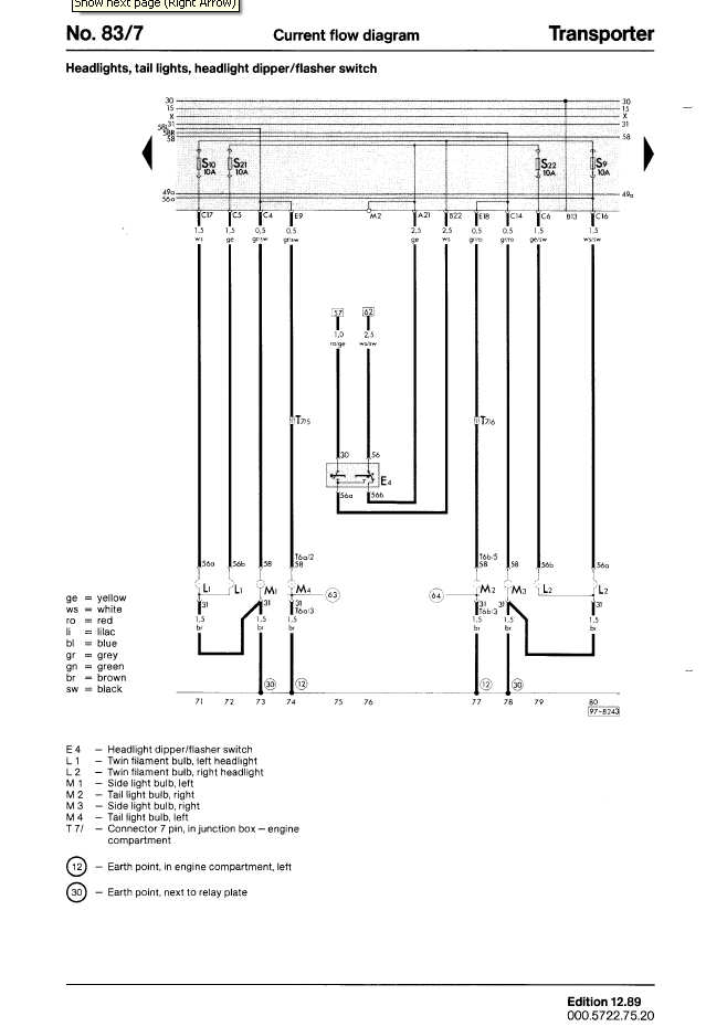
There is a Black box on the left hand forward side of the engine bay (junction box). This contains most of the wiring as it comes from the front of the van in the loom to the rear. It also contains a 50 AMP strip fuse for the glow plugs and the solenoid for the glow plugs, aux pump relay and the round 7 pin connectors too. It's a good idea to keep the cover for this box as once its lost moisture gets in here and causes grief.If you have a turbo engine there is an auxiliary coolant pump that fires in if the engine stops and the engine is still hot (>107 deg C) and circulates coolant until the engine cools down a bit. (Syncros also have a fan blower on the turbo for extra cooling) There is also a round 7 pin connector that carries the feeds for the rear lights There is also an Earth point on the left hand side on the engine bay with about 4 Earths connected this gets crudded up and corroded its a good idea to clean it up and remake the connection or extend the earths neatly back to the neg post on the battery. This handles some important stuff like your coolant level sender so its a good idea to check it if you have unwanted engine electric behaviour. There is also a heavy duty Earth strap from the engine block to the neg battery terminal and the gearbox nose earth strap that are the path that the starter motor will take.
Browns are Earths.
The thickest (10 gauge)red goes from the alternator to the positive on the battery black live with ignition fuel cut of solenoid on the fuel pump.
feed to glow plugs from the glow plug relay is red ( 4 gauge)
white/blue temperature sender for glow plugs
brown/red feed to temperature sensor for the auxiliary pump and the high current side of the aux pump relay (inside junction box comes from glow plug relay)
red/black aux pump relay switching side (comes from glow plug relay)
a red is for auxiliary pump positive side and brown/red for the negative.
T7a = 7 pin round connector in the junction box
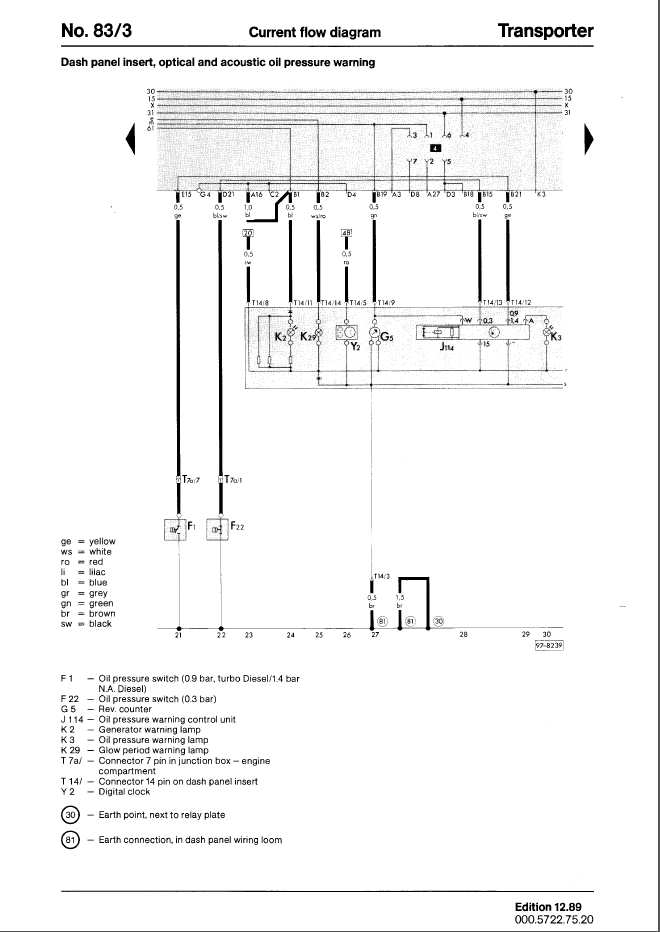
T7a 7 Oil pressure switch High revs yellow
T7a 6 Red white is for the auxiliary pump solenoid
T7a 5 W connector on alternator (rev counter) is green on the forward end then red white to the alt
T7a 4 earth
T7a 3 blue/green coolant shortage level sensor
T7a 2 yellow/red coolant temperature sender
T7a 1 blue/black is low pressure oil sensor low revs (note same colours used for reverse lights)
T3/1 black to D connector on alternator (charging light on dash)
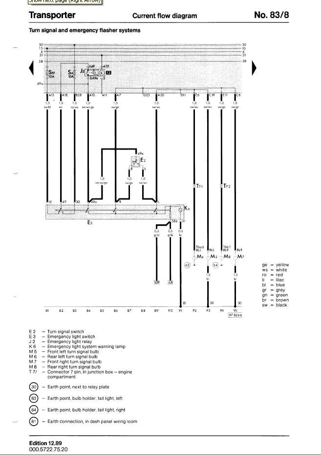
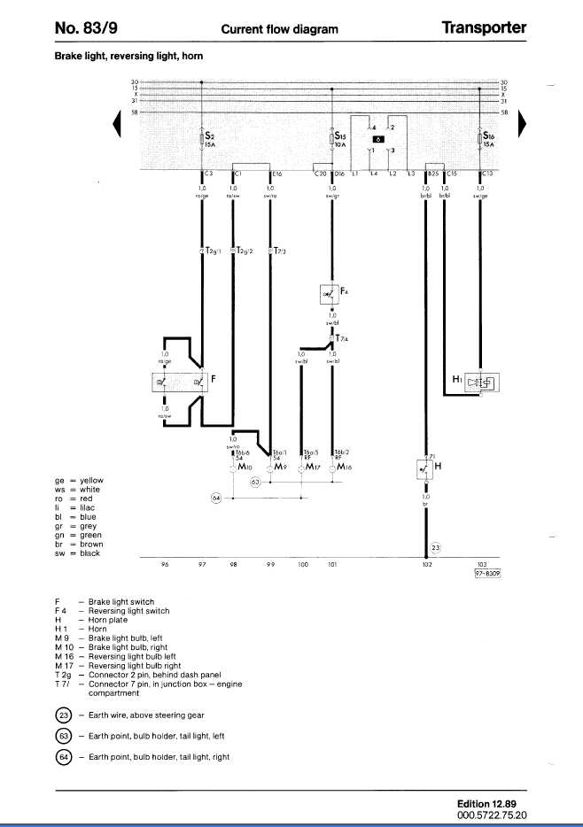
T7 Round 7 pin connector that handles Lighting
T7 7
T7 6 grey/red tail light right
T7 5 grey/black tail light left
T7 4 black/blue reverse light
T7 3 black/red brake light
T7 2 black/green rear right turn signal
T7 1 black/white rear left turn signal
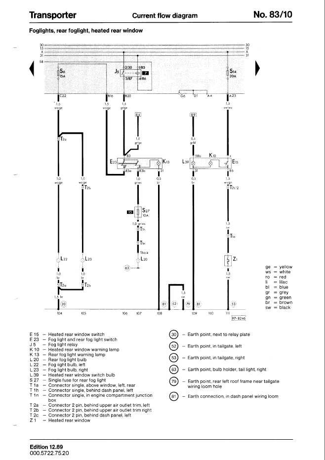
grey/white is fog light single connector in black box
Diesel Glowplug Wiring
Clinthefox
Diesel glow plug wiring
L white/red to indicator light
T Blue/white to temp sender
50 Red black to starter trigger
85 Brown to earth
87 Big fat red to glow plugs
30 Big fat red from fuse
86 Black from ignition
Wiring Diagramss
KY and JX diesel
