VW Electrics fuse box: Difference between revisions
From VW T25(T3)-Tech
Jump to navigationJump to search
No edit summary |
No edit summary |
||
| Line 9: | Line 9: | ||
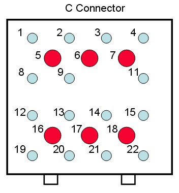
<li> All connectors number the pins from top left to bottom right as shown above. | <li> All connectors number the pins from top left to bottom right as shown above. | ||
<li>Pin 10 is missing but the numbering is not disrupted by this. | <li>Pin 10 is missing but the numbering is not disrupted by this. | ||
<li>This logic applies to all the connectors on the fusebox.< | <li>This logic applies to all the connectors on the fusebox.<p> | ||
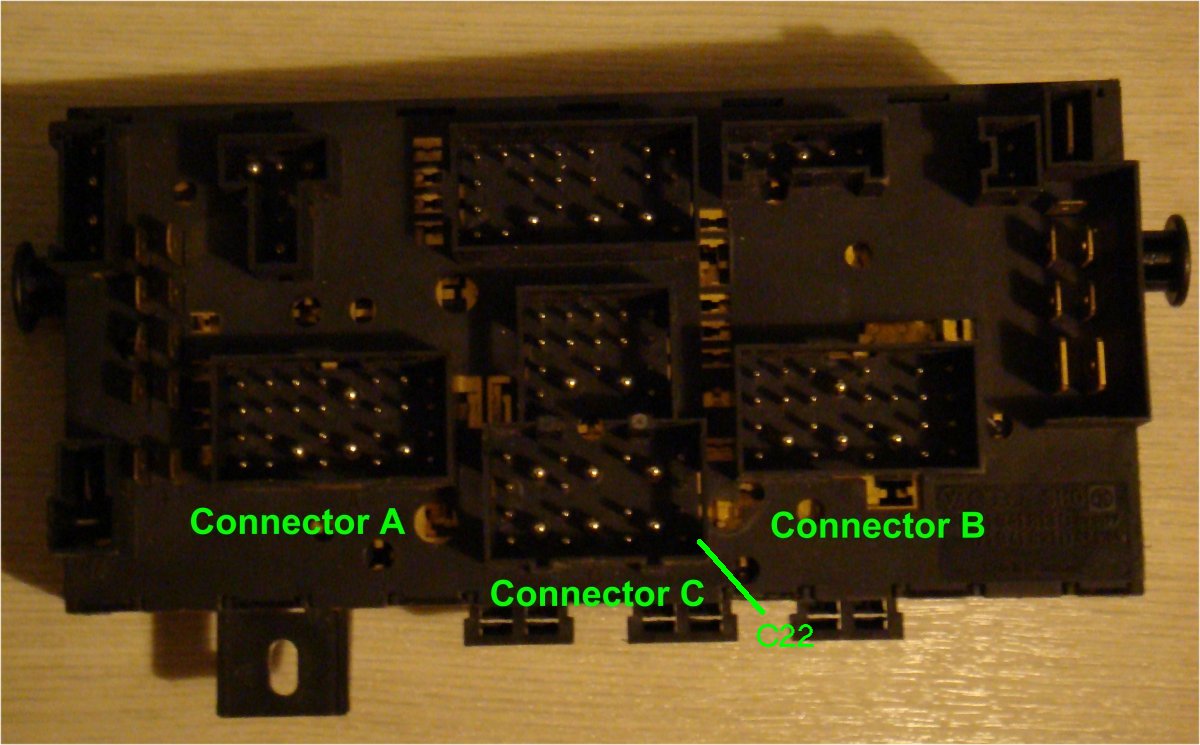
'''Photo of the rear of a late T25 Fusebox - see connector C''' | |||
[[Image:Fusebox_rear_view.jpg]]<p> | |||
'''Note on Foglight Fitting'''</p> | '''Note on Foglight Fitting'''</p> | ||
The foglight +ve feed from the 1st position on the foglight switch comes out of Pin 22 on Connector C (via fuse 6 and needs a relay fitting to position 7). Relay 7 is driven by the sidelights so the foglight power is only connected once the sidelights are on. Use this feed from connector C to drive the relay for the foglights. | The foglight +ve feed from the 1st position on the foglight switch comes out of Pin 22 on Connector C (see above - via fuse 6 and needs a relay fitting to position 7). Relay 7 is driven by the sidelights so the foglight power is only connected once the sidelights are on. Use this feed from connector C to drive the relay for the foglights. | ||
Revision as of 18:22, 2 February 2008
Waterboxer fuse locations http://homepage.ntlworld.com/robertj.green/T25/Knowledge%20base/electrical-Fusebox-locations.jpg
Fusebox Connector Description
The pin arrangement for the connector C in a late model fuesebox is shown below
Notes
Photo of the rear of a late T25 Fusebox - see connector C

Note on Foglight Fitting
The foglight +ve feed from the 1st position on the foglight switch comes out of Pin 22 on Connector C (see above - via fuse 6 and needs a relay fitting to position 7). Relay 7 is driven by the sidelights so the foglight power is only connected once the sidelights are on. Use this feed from connector C to drive the relay for the foglights.
