Sorry for the time lag replying.
Normally at work I would confirm the gas valve is not opening by setting up a pressure test and then watching to see if it drops (or not) while the heater is opperated.
More questions
I assume you have tried it in the high and low flame settings with the same result ?
If you set the switch to fan only, low and high, do you get air out of the hot air vent(s) at 2 different speeds ?
Technical stuff
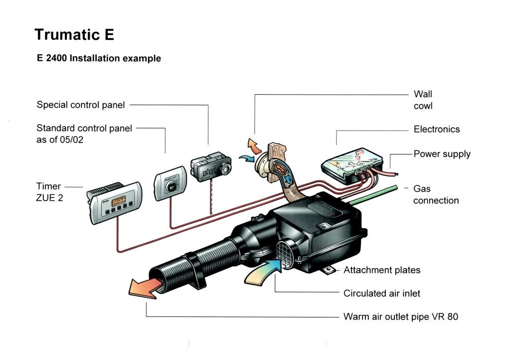
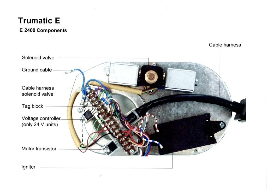
The heater has a double gas valve with 2 solenoids on it, one for the low setting and one for the high setting.
It has a single motor with 2 fans attached to the spindle in different sealed chambers of the heater. One for the burner air supply and one to circulate the hot air round your van.
The motor speed is controlled by the pcb and a power transistor.
The pcb monitors the motor speed and shuts down the heater by closing the gas valve if "thinks" the motor is not drawing the correct amount of power for the speed set.
Possibilities
If the heater has been out of use for a long time the gas valve may have stuck closed ,
unlikley but worth giving it a tap or two with a SMALL hammer while the ignitor is running.
Again due to lack of use, the motor bearings/ seals may be tight causing the motor to draw to much power. The pcb would prevent the gas valve from opening during the light up sequence so the heater fails to light.A good blow out with an air line might help , but I have found that the cure is short lived

You could have a pcb fault with the motor speed sensing.
It could be the speed control transistor.
It could just be a broken wire or bad connection somewhere.
Also just a reminder of the initial checks Truma recommend,
Check voltage at the heater as you try to run it.
Check gas supply is good at the heater.
Its all to easy to get excited about complicated stuff and forget the basics.
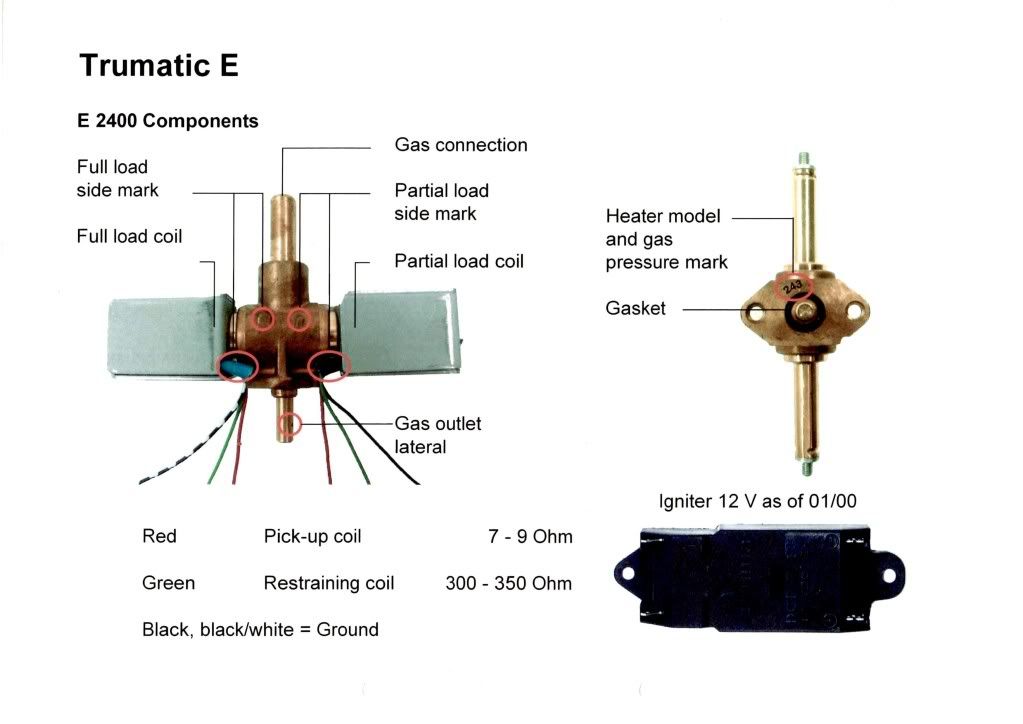
These are from trumas training manual and may or manot be of use.
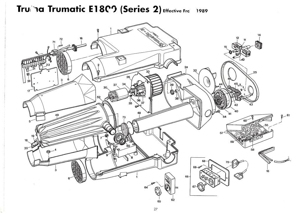
Note that the 1800 and 2400 are very similar
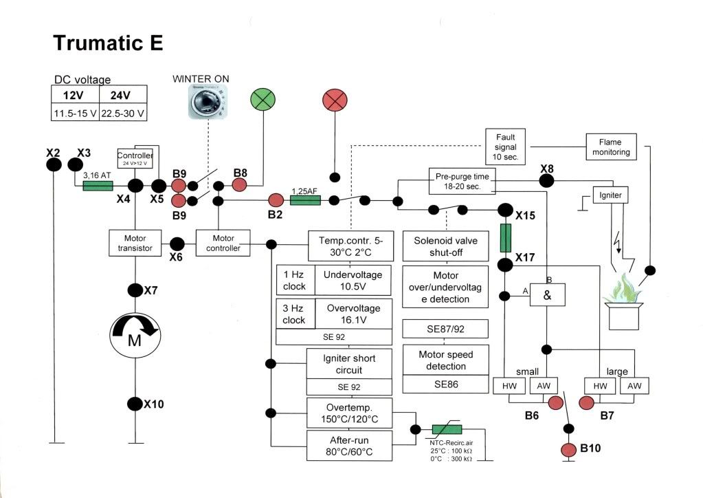
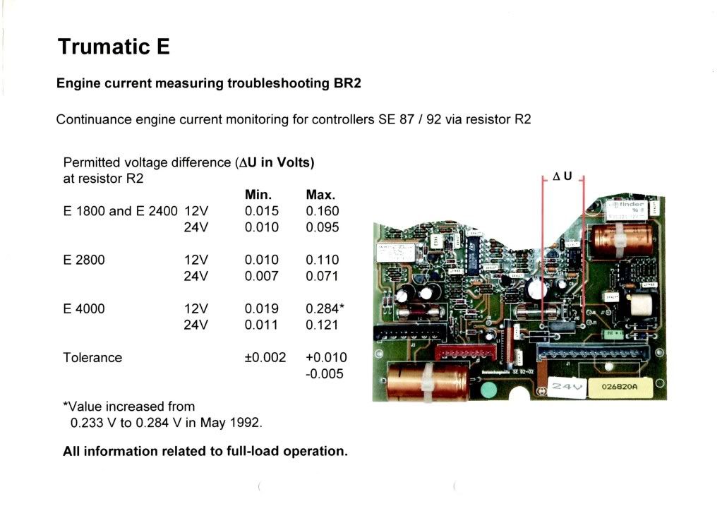
This last page may be of use for checking monitoring of the fan motor, the picture shows the pcbin the remote box.
I believe there is a page missing which has wiring information for the connectors , referred to in the flow diagrams by the "X" & "B" numbers. if I find it I will E D I T and add it to this post
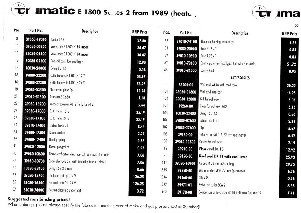
E1800 parts diagram