Page 1 of 2
The haynes wiring diagram.. project
Posted: 02 Mar 2012, 13:36
by kevtherev
Those of you who struggle to comrehend the diagrams, but would like a simpler version to use.
I thought that some of us who do get it can take one page each and redraw it in a simpler form.... what do you think?
Re: The haynes wiring diagram.. project
Posted: 02 Mar 2012, 15:28
by jamesandtheopenroad
Sounds great. Off you go...

As someone who knows feck all about wiring diagrams but can see what to do when it's infront of me, that would be really handy.
Re: The haynes wiring diagram.. project
Posted: 02 Mar 2012, 20:50
by edoh
would be brill - if you/others are up to it -

Re: The haynes wiring diagram.. project
Posted: 02 Mar 2012, 21:01
by bigherb
I have done the early diagrams the same as my Bay window book.
They are in a cad program so lose the sharpness converted to jpeg but they are like this.

Re: The haynes wiring diagram.. project
Posted: 02 Mar 2012, 21:31
by kevtherev
Now that's what I'm talkin' 'bout
great post Big herb
Re: The haynes wiring diagram.. project
Posted: 02 Mar 2012, 22:50
by CovKid
I wouldn't knock yourself out. The late bays used same colour coding - you just have to add in whats not there if you really want to go that far. I have a laminated one I still use even today and never actually found a need to rewrite it as the additions are just supplementary circuits and relatively simple anyway.
Re: The haynes wiring diagram.. project
Posted: 03 Mar 2012, 08:40
by kevtherev
Nice one cov kid.
let's have them
I did a couple using paint rudimentary I'll admit but effective .
Ill post it up when I'm home next
Re: The haynes wiring diagram.. project
Posted: 03 Mar 2012, 08:45
by ghost123uk
Great idea in principle Kev, but finding someone who actually understands the Heynes offering might be a challenge

I have a background in Electronics and can read and understand a circuit diagram of, say a complex Ham Radio or a Hi-Fi amp, as easily as I can read a road map, but I cannot get my head round the Haynes ones !
When it comes to vehicle electrics, I just rely on what I know and my trusty Avo meter !
If it could be done, it would be great
Re: The haynes wiring diagram.. project
Posted: 03 Mar 2012, 13:11
by jamesc76
As a mechanic I understand um fine! But then I have too, for me to re right it out would confuse me more
Re: The haynes wiring diagram.. project
Posted: 03 Mar 2012, 17:40
by PetenAli
At the moment I could use a simplified diagram to help sort my non-functioning horn.

The Bentley has got too many options so sat here with the Haynes trying to work out:
1) I understand that the horn works when the horn button is pressed and that goes to earth. Is it the earth from the horn itself that runs through the horn push or the earth from the relay? (Or does the relay earth to one of the crowns behind the fuse box?)
2) Why I have power at the fuse (with ignition on) but not at the terminal on the horn - the Haynes suggests its a straight run from fuse to terminal.
3) Where does the trigger power for the relay come from?
4) Should I be able to feel the horn relay click when I press the horn push (with ignition on)? I can't at the moment so that might be my answer.
And just as an aside... why have I got dual tone horns fitted but only wiring for a single horn? Mr Haynes shows dual tone horns so if I could get twelve volts down there then it would be straightforward to wire in the second horn. Currently I have a black / yellow cable to the horn and a brown / blue from the horn (presumably to an earth somewhere).
I probably should start a thread on this - it might be a bit of hijack but I read Kev's initial thread just at the right time.
Any thoughts very gratefully received as ever. Could the moderators tell me if this is a hijack and I need to start a thread of my own?
Thanks,
Pete
Re: The haynes wiring diagram.. project
Posted: 03 Mar 2012, 18:14
by kevtherev
I think and I'm sure you do that your problems are a separate issue

Re: The haynes wiring diagram.. project
Posted: 03 Mar 2012, 21:26
by Nij
I find the haynes easy enough but happy to assist if you require
Re: The haynes wiring diagram.. project
Posted: 04 Mar 2012, 07:06
by CovKid
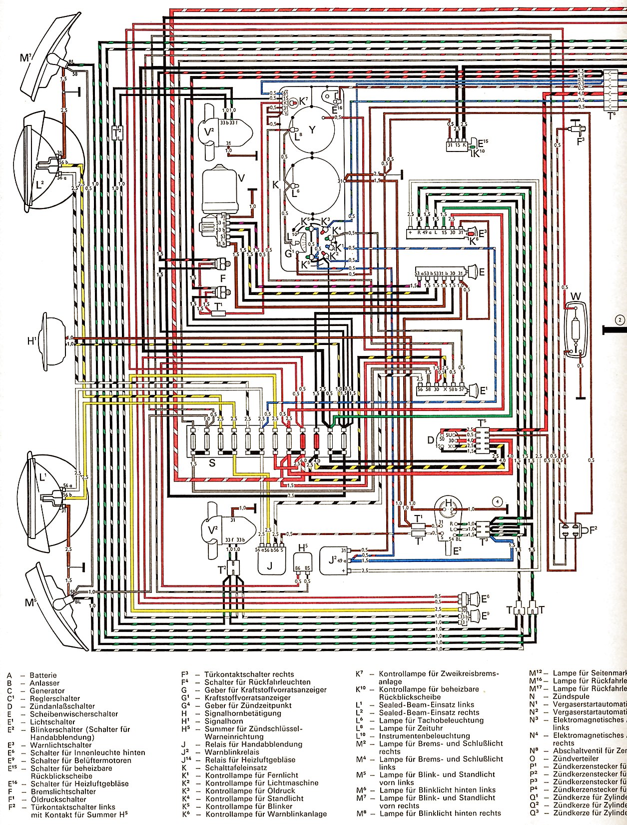
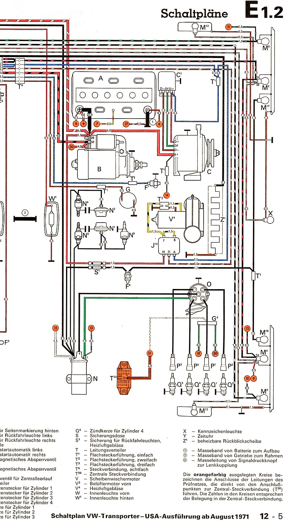
http://www.vintagebus.com/wiring/Transp ... 1971-1.jpg" onclick="window.open(this.href);return false;
http://www.vintagebus.com/wiring/Transp ... 1971-2.jpg" onclick="window.open(this.href);return false;
Not much has changed so what's the problem.
Loads on
http://www.vintagebus.com/wiring/index.html" onclick="window.open(this.href);return false; - no point in trying to reinvent the wheel. Lighting, indicator and horn circuits are virtually identical even down to colours. Anything else is incidental really.
Find one with an alternator (ideally), print it in colour and laminate it. Had mine for a very long time and its tucked inside my haynes should I ever need it. Saves much searching.
Theres also this (88 Vanagon) which includes info on how to read modern schematics:
http://mysicka.ics.muni.cz/Bus/material ... agrams.pdf" onclick="window.open(this.href);return false;
Re: The haynes wiring diagram.. project
Posted: 04 Mar 2012, 10:18
by OddJobBob
I think such a project would be great. I know when I had a problem with my coil I spent ages studying the various Haynes diagrams but still could not fully comprehend them, especially when the wiring disappeared to the top and bottom of the pages. Kevtherev helped me out with an explanation. If you take time looking at the key and drawing in pencil on the page, most bits make sense except, as I say, where the lines end at the top and bottom of the pages.
Rob
Re: The haynes wiring diagram.. project
Posted: 04 Mar 2012, 11:25
by Hacksawbob
Just to throw an idea into the ring, anyone familiar with augmented reality? I wonder if it could be done so you point your smart phone at an engine bay and up pops the relavant diagram for the components Aurasma is free... might give it a go

not sure if it would be flxible enough to account for different engine bay color and oilyness though!