I can see 4-pin wiring in the Bentley manual.
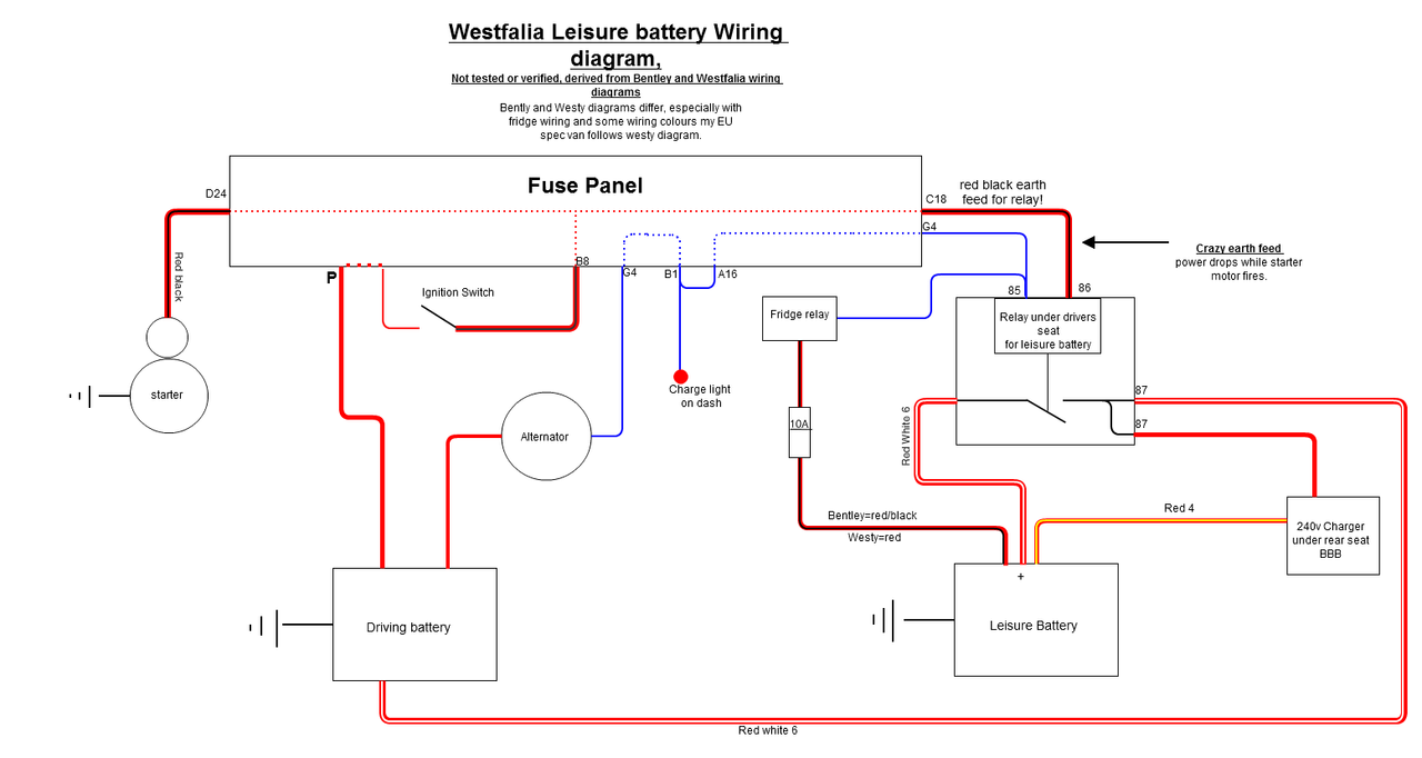
Fat Red - to starter battery "+" - Terminal 30
Fat Red / White - to leisure battery "+" - Terminal 87
Blue wire - To alternator - Terminal 86
Charge light wire - relay is energised when charging (engine running).
Fat Red / Black - to starter "50" terminal - relay Terminal 85.(which doesn't make much sense to me).
I presume the 5th pin on the relay is either another Terminal 87, therefore another out put when charging.
Or a Terminal 87a, which cuts the output voltage when charging.
Otherwise - what colours do you have?
If you have a brown wire, then that would go to Terminal 85 instead - relay ground.
I am not sure if you can see it, but I believe this is the correct schematic. From the wiki...
Quite common on these VW relay diagrams, for terminals 85 and 86 to be swapped around.
Also just as common to see 30 and 87 swapped too.
86 should be powered feed to relay control.
85 should be ground / earth.
30 should be main feed.
87 should be output voltage to the load.