Page 1 of 3
2.1 DJ Coolant System Layout Help Needed
Posted: 09 Mar 2023, 22:11
by Latenights
Hi All,
I've scoured the forums, Google and YouTube trying to find a solution to my quandry and have decided I need to just ask for help.
I'm swapping out my 1.9 DF WBX with the 'old' coolant system and am putting in a rebuilt 2.1 DJ with digijet with the 'new' system.
I already have a DJ engine to part-ex, which was in good running order when it was taken from a scrap van. But even though I made it clear when I watched it being hacked out that I needed (and was happy to pay extra for) everything to be able to swap it into mine it appears that some key parts were left out of my basket that day!
I have the bleed rail but don't know what it actually attaches to in the van, as in how it attaches to the bodywork (a post mortem of the butchered pipes has helped identify where most of the pipes attached to the tail go. I've also managed to buy a brand new expansion tank and lid, and have a list of (most of) the new hoses I'll need.
I appear to be missing a part described by its own name on each sellers site, sometimes called the "coolant distribution manifold", or "water junction", or "coolant flange" or anything else. The part number for one iteration of it is 251 121 438. Acquiring one doesn't seem too difficult, but knowing where to put it has me stumped. I've looked at hundreds of photos of engine bays and haven't spotted one yet!
Neither the bleed rail nor the distribution junction appear to be unique to the DJ as they seem to be standard on all petrol engines from 1985 onwards. Any help in identifying where they go exactly would be greatly appreciated. Photos would be a lifesaver.
Also, while you're here, do I **NEED** to upgrade the 32mm pipes running to the radiator for 38mm? The ones I have in the van already are stainless steel, so while I have 38mm plastic replacements ready to use it would be a shame to swap them out if not necessary.
Thanks in advance to any wise sages or amateur photographers who may be able to assist.
E D I T - forgot to mention I'm running on a 4 speed manual gearbox.
Re: 2.1 DJ Coolant System Layout Help Needed
Posted: 09 Mar 2023, 22:18
by Stesaw
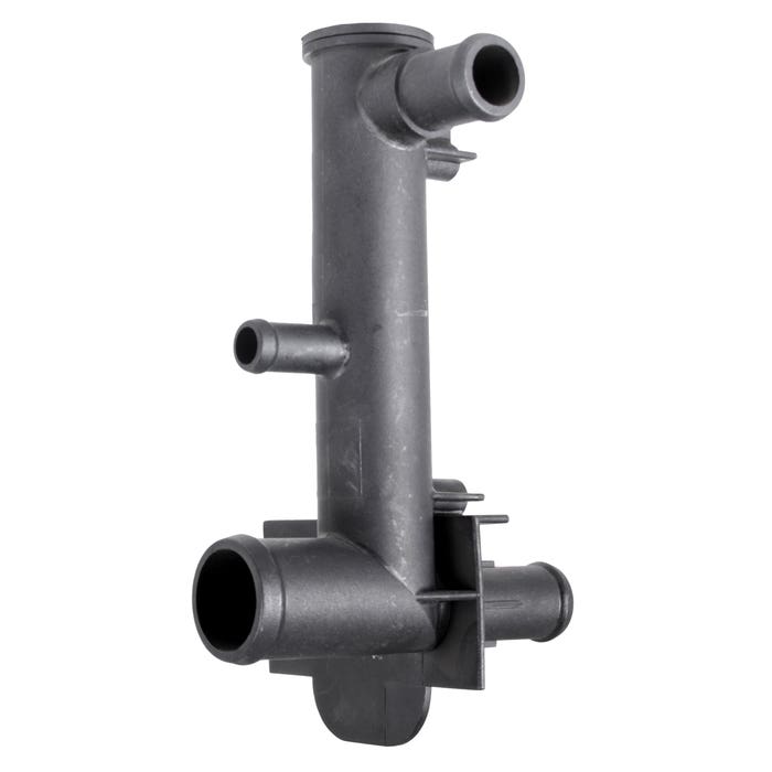
That's the junction you are refering too, now heres the thing theres three versions. An early, a early late and a late late.
As I found out the early late and late late have a different pipe that goes to the right hand head (one is longer than the other)
As for where this goes..

Sits behind that panel in the engine bay circled held in place with two bolts if I recall.. the bleed rail attaches to it at the top then radiator line and also heater core pipes.
Re: 2.1 DJ Coolant System Layout Help Needed
Posted: 09 Mar 2023, 23:01
by Mocki

Or

Re: 2.1 DJ Coolant System Layout Help Needed
Posted: 10 Mar 2023, 09:05
by shepster
Reference water pipes, my '84 van has the 32mm stainless pipes with a later 2.1 with no issues, having said that the entire cooling system is all early.
Re: 2.1 DJ Coolant System Layout Help Needed
Posted: 10 Mar 2023, 20:47
by Latenights
@Stesaw, Thank you so much for the prompt reply and the photo – it’s kind of obvious now why I never spotted it behind the bulkhead there in the hundreds of photos of engine bays I’ve looked at!
I was half hoping that it was hiding somewhere under the air filter housing, but neither location is ideal as my LPG system is taking up real estate in both areas. Fortunately (well, for the bus at least, not my bank account) I’m having a new LPG system that I’m told will work with the digijet system and get close to the theoretical 112 bhp that running on petrol would give, so at least I can try to fit that system in around the new cooling setup.
I’ve read on Brickwerks about the early-late and late-late cooling systems and apparently the way to tell if you have the early-late system is by the plastic thermostat housing in the front left and gearbox number. The front left plastic thermostat housing is what I have on the donor 2.1DJ, so I assume it had the early-late cooling system (no idea what the gearbox number would have been unfortunately). It might have been helpful to know what the distinguishing feature of the late-late cooling system is just to be sure which I’m supposed to be running.
I’m wondering if maybe Brickwerks have it wrong somehow? After all, the schematics that @Mocki shared for the non-synchro DJ coolant layout has a matching bleed rail setup to my current engine, with two hoses coming from the thermostat housing to the bleed rail.
The photograph of the engine bay that @Stesaw shared shows only one hose to the bleed rail, and as there is a carb fitted I can only assume it’s a DF or a DG. Brickwerks list a different thermostat housing for the DG/DF to the DJ, and say that previously a modification to the DJ version was needed to fit a DF/DG because you couldn’t get DF/DG ones any more. For the “alternative” variant of thermostat housing they sell for the 1.9 engine the only difference they list is that it doesn’t have a connection to the oil cooler, which the 2.1 engine version does have. None of the thermostat housings are described as being early-late or late-late, which suggests that they remained the same throughout after the change from early to late systems.
If no additional hose connections exist elsewhere in the system then why the extra nozzle on the “early-late” junction?
This observation leads me to believe that the actual difference between what Brickwerks refer to as the “early-late” and “late-late” coolant systems is actually as simple as whether the bleed rail has two hoses connected to the thermostat housing or just one. If the second hose that connects to the bleed rail on late-late systems instead connects to the middle connector of the junction on early-late systems, then this would account for the extra spout no longer being needed on the late-late version of the housing.
Hopefully someone can confirm this observation for me?
Essentially, if the bleed rail has only one hose to the thermostat housing does the coolant junction have the extra spout in the middle. Conversely, if the bleed rail has two connections to the thermostat housing does this mean the junction has no middle spout?
Now that I’m pretty confident I know what parts are missing from my coolant system and, more importantly for my sanity, where they actually fit, what I can’t for the life of me figure out is where the top hose that fades from grey to white connected to the junction on the second picture shared by @Mocki would connect to. Every variation of the 1985 onwards style cooling system schematic for petrol engines that I’ve seen (and I’ve seen a lot by now!) even those for Synchro models (as per the first schematic shared) shows this exact same hose to nowhere…
Apart from that hose, I think I have all the hoses on the junction accounted for – one from rad to junction, one from junction to right hand cylinder head, one from heater matrix to junction, one to bleed rail. 4 hoses total by my count.
The headache that this is causing is almost enough to consider @shepster’s post about having the early coolant system on the DJ – at least I know that I have all the parts for that. Unfortunately I’ve read a thread by @Robsey about trying to fit an early DF cooling system to a DJ running digijet injection and he ended up with a hybrid DH cooling system. Since I have most of the DJ system and don’t mind buying new hoses (no point having the 40 years of muck in my old system pumped through my shiny new engine!) I’m still minded to press on with the later coolant system.
I’ll be gutted to have to swap out those 32mm stainless hoses for plastic ones though ☹
Thanks to all who responded – It’s greatly appreciated.
Re: 2.1 DJ Coolant System Layout Help Needed
Posted: 10 Mar 2023, 22:51
by Mocki
I think you are having a few crossed wires with terminology here .
Early cooling system 82-84 has two big rubber rad hoses around the front of the engine bay with rubber spigots for the t bleed and metal thermostat housing on water pump at rear of engine
Late Early is the same but has plastic bleed joiner in the big rubber rad hoses
Early Late has metal bleed ring around the engine bay and plastic thermostat housing on front of LHS head and separate water pump at rear of engine
Late Late has plastic bleed ring , plastic thermostat housing
DH , SS , MV and DJ thermostat housings have extra spigot .
Bear in mind many DJ , SS, MV engines now have DG carbs fitted and injection binned long ago
Re: 2.1 DJ Coolant System Layout Help Needed
Posted: 10 Mar 2023, 23:07
by Latenights
Mocki wrote: ↑10 Mar 2023, 22:51
I think you are having a few crossed wires with terminology here .
Early cooling system 82-84 has two big rubber rad hoses around the front of the engine bay with rubber spigots for the t bleed and metal thermostat housing on water pump at rear of engine
Late Early is the same but has plastic bleed joiner in the big rubber rad hoses
Early Late has metal bleed ring around the engine bay and plastic thermostat housing on front of LHS head and separate water pump at rear of engine
Late Late has plastic bleed ring , plastic thermostat housing
DH , SS , MV and DJ thermostat housings have extra spigot .
Bear in mind many DJ , SS, MV engines now have DG carbs fitted and injection binned long ago
Thanks!
I did read about the early-early and late-early coolant systems but didn't want to confuse matters as I'm trying to move away from those.
Brickwerks say that if you have the plastic thermostat housing at the front left (and the gearbox code) then you have an early-late system. Your descriptions seem far better - plastic bleed ring (check), plastic thermostat housing (check).
So I take it that my engine is on the late-late system and so the junction I need won't have the extra spout in the middle. I'm guessing the "hose to nowhere" on all the schematics is an artefact that I don't need to worry about.
By chance I've just come acorss another of your posts:
Mocki wrote: ↑23 Dec 2022, 23:48
If you were to follow this theory , you would have no heater un till the thermostat opened , and would not be Able to switch the heat off at all .
The heater pipes feed direct not via the thermostat and return to the cold side of the system

I think this really simplifies the system to a level my feeble brain can process. The thermostat housing has all the connections I would expect, including what looks like the purple pipe heading in the direction of the coolant distributor. I hadn't accounted for that one in my list at the end of my last post, so the coolant distributor should have 5 outlets? Does that sound right?
Re: 2.1 DJ Coolant System Layout Help Needed
Posted: 10 Mar 2023, 23:57
by Mocki
Only automatic transmissions have the five spigots on the distribution towers iirc
Re: 2.1 DJ Coolant System Layout Help Needed
Posted: 11 Mar 2023, 09:45
by Latenights
Mocki wrote: ↑10 Mar 2023, 23:57
Only automatic transmissions have the five spigots on the distribution towers iirc
I think I made a fundamental mistake that is now breeding unnescesssary confusion.
Looking at the two variants on the brickwers site, the
early-late and the
late-late both have 5 spigots (the 5th, not shown on your flow diagram, goes to the bleed rail) of comparable size from one variant to the other. The difference is that the spigot halfway up the shaft on the early variant has been moved to the bottom plate on the late variant, and the position of the spigot that returns to the right cylinder head has moved over. This would explain the observation by @stesaw that the late-late needs a longer hose to connect to the cylinder head.
I don't know why, but I assumed that the spout halfway up the shaft of the early-late version was an extra spout, not simply in a different position. I'm assuming that this particular spout is the feed to the heater matrix which will have enough play over its 3 metre or so length to be able to attach to either position.
Now that I understand the difference, what I can't understand is why the automatic gearbox version retained the basic design of the "early-late" with the heater matrix spout halfway up the shaft and the need for the shorter connecting hose to the cylinder head. As I don't have an automatic I won't dwell on that any longer!
I was also getting thrown by the fact that the plastic bleed rail on my DJ has two connections into the thermostat housing whereas the schematics for the 1900 engines and @stesaw's photograph of an actual engine bay show only one. I figured that as the thermostat housing was the same (other than oil cooler attachment, which is accounted for) then that hose had to go somewhere and assumed they just took it to the distribution junction. Looking closer I think the two connections to the bleed rail on the DJ is because it doesn't have any coolant attachements to the inlet manifold as per the DF/DG. I missed that the hose from the water pump to the header tank has a take off for the carb on it in the DF/DG schematic, so this brings everything back into balance.
So I suppose this is the really long answer to my original question, which variant of the distribution junction do I need and where does it sit?
The short answer was gven by @stesaw in his first reply - it sits where he showed in the photograph and it doesn't matter which variant I use as long as I have the correct hose to the cylinder head.
Going through the thought process of the long answer has helped identify what I need to consider for my second question as to whether to change the stainless steel 32mm pipes to the radiator.
First off, the "early" system on my current DF would need some modification for the digijet system, as @Robsey points out in
his thread. I applaud his efforts to find a solution by using parts from a DH engine, but if I can keep the van with one type of cooling system then it should make my life easier if I need to find spare parts, and will certainly be of benefit to any future owners who would have a hell of a job figuring out what mods I'd made.
Next problem, the stainless pipes terminate inside the engine bay, so if I want to keep them it'll have to be a case of cut them back and find a reducing hose to connect from the thermostat housing and the distribution junction. Possibly the ones from the late system that attach the front end of these hoses to the radiator. This level of mod I can live with!
Third, I think VW increased the bore so that coolant would be encouraged towards the rad instead of through the bypass per the coolant flow diagram. Except that the rad connections on the late system seem to have remained as 32mm, so it reduces to the smaller bore at the front end anyway, and in a pumped system would that make so much of a difference as the bottleneck remain the same? (Albeit 3 metres longer in each direction!)
The simple answer for me is - ask the guy who is giving the warranty on my rebuilt engine! If he wants 38mm pipes to honour the warrany then that's what I'll put. From the conversations I've had with him I think I can trust his judgement on this, and if I get into any bother then I have the plastic 38mm ones to slot in if needed.
Thanks again to all who contributed to my understanding of the difference between the various systems and how they'll affect my engine swap

Re: 2.1 DJ Coolant System Layout Help Needed
Posted: 11 Mar 2023, 15:34
by shepster
I know I'm biased but I really can't see what you're trying to gain, I've had an early (late) cooling system with a 2.1 running on a carb for about 16yrs without a single issue. I even managed to plumb the oil cooler thing in.
All the best anyway.
Re: 2.1 DJ Coolant System Layout Help Needed
Posted: 11 Mar 2023, 18:17
by Latenights
shepster wrote: ↑11 Mar 2023, 15:34
I know I'm biased but I really can't see what you're trying to gain, I've had an early (late) cooling system with a 2.1 running on a carb for about 16yrs without a single issue. I even managed to plumb the oil cooler thing in.
All the best anyway.
I do appreciate the advice, really I do, but the issue isn't with a preference for a late system over an early one, it's that the early system is missing a location for a second sensor needed for the injection system according to this
thread.
I don't have a Pierberg carb, manifold or other ancillaries I might need from a DG (the DF uses a different setup which many recommend against putting on a DJ) and the advice I've had is that a working injection system (which I do have) is preferable to a carb setup anyway.
While I'd be prefectly happy with an early cooling system if I could get it to work, I don't want the hassle of trying to locate parts from a DH engine as the other guy had to in order to get the fuel injection working. Especially when I already have most of the late cooling system on the DJ engine already, and spare parts will hopefully be easier to source than for the hybrid DF/DH setup I'd otherwise need.
Thanks again though
Re: 2.1 DJ Coolant System Layout Help Needed
Posted: 11 Mar 2023, 19:25
by Robsey
As it happens, I finally got a cross-engine pipe last week.
All painted and ready to fit.
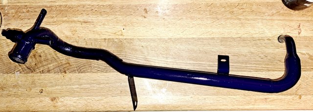
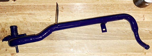
And I have also drilled and tapped the thermostat / water-pump castings for the temp 2 sensor.
(Pictures to follow when I at the unit on Tuesday).
I plan to assemble the water side of things this year.
Re: 2.1 DJ Coolant System Layout Help Needed
Posted: 11 Mar 2023, 19:38
by Mocki
A completely irrelavent note to this thread, the DF and DG cross pipes ( as in Robseys picture above ) are different
Re: 2.1 DJ Coolant System Layout Help Needed
Posted: 11 Mar 2023, 22:06
by Robsey
They are, but it is easier for me to modify a carb cross pipe, than it is find an injection cross pipe.
Obviously the mount legs are slightly different, and the carb pipes have stubs for carb heating etc.
So for me, it will be a matter of modifying the mounting legs, and blanking off the carb stub.
Re: 2.1 DJ Coolant System Layout Help Needed
Posted: 12 Mar 2023, 11:27
by ajsimmo
I'm late to the party, but I understand you want to fit a DJ with digijet in place of a DF?
As a consequence you feel you need to also swap the cooling system? If so, that isn't strictly necessary. Another option is to just use the early cooling system on the DJ, and maybe re-purpose the carb choke heating circuit for the oil cooler instead. Alternatively you could opt to fit an external oil cooler. This would seem a much more straightforward and cost effective solution.
Just drill and tap the thermostat housing for your early DH & Syncro style screw in temp 2 sender.
Sent from my moto g(30) using Tapatalk