What a lift does to your syncro's suspension geometry
Posted: 02 Jun 2013, 16:57
Further to recent late night waffle in another topic, here's someting to consider with a nice simple diagram:

Consider what happens as you raise a T3: the wishbones start to point up even more, point A (the instantaneous centre) goes up, and so R (the roll centre) also goes up. Point C is the theoretical centre of the tyre contact patch. The relationship of R to the COG of the vehicle is important for good handling and roll control of the body. Ideally they want to be as close together as possible, to minimize the "Moment arm" or the leverage that the body has over the suspension system.
Note that A and R move about quite a bit on a vehicle like ours that has a fair bit of suspension travel.
The rear end is another matter entirely, because it's semi-trailing with built-in anti-squat (the fore-aft offset on the swingarm bushes) so the geometry has to be plotted out in plan as well as on-axis (you actually have to do this with true double wishbones too as they are often inclined to introduce some anti-dive):
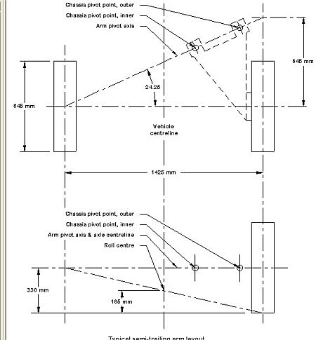
The arm pivot axis could reasonably be struck though the centre of both bushes on our suspension.
Then we move onto the roll axis! This is a line struck though the front and rear roll centres and is usually considered to be a good thing if inclined downward at the front end. A nice diagram with a van in it:

The next step would be to take the basic measurements from a standard and lifted syncro on level ground and find out what really happens...
Consider what happens as you raise a T3: the wishbones start to point up even more, point A (the instantaneous centre) goes up, and so R (the roll centre) also goes up. Point C is the theoretical centre of the tyre contact patch. The relationship of R to the COG of the vehicle is important for good handling and roll control of the body. Ideally they want to be as close together as possible, to minimize the "Moment arm" or the leverage that the body has over the suspension system.
Note that A and R move about quite a bit on a vehicle like ours that has a fair bit of suspension travel.
The rear end is another matter entirely, because it's semi-trailing with built-in anti-squat (the fore-aft offset on the swingarm bushes) so the geometry has to be plotted out in plan as well as on-axis (you actually have to do this with true double wishbones too as they are often inclined to introduce some anti-dive):
The arm pivot axis could reasonably be struck though the centre of both bushes on our suspension.
Then we move onto the roll axis! This is a line struck though the front and rear roll centres and is usually considered to be a good thing if inclined downward at the front end. A nice diagram with a van in it:
The next step would be to take the basic measurements from a standard and lifted syncro on level ground and find out what really happens...