Page 1 of 1

Let's work together to try to understand Haynes circuits

Posted: 09 Mar 2013, 15:26
by ghost123uk
Let's try and work together to understand Haynes circuit diagrams, it would benefit many ;)

I know lots has been said about them, and some have said "could you do better?" but lets see if we can, between us, get to understand them.

I have a good background in both fine electronics and vehicle electrics. I usually find it easier to figure it out for myself :roll: but there are times where the details in the Haynes could be useful, if only we could understand them better !

If we do this methodically and avoid wandering into off topic discussions, it might be worth condensing and putting in the wiki ?

~~~~~~~~~~~~~~~~~~~~~~~~~~~~~~~

I understand some / much of it but there are bits that puzzle me.

Can I give an example to start with =

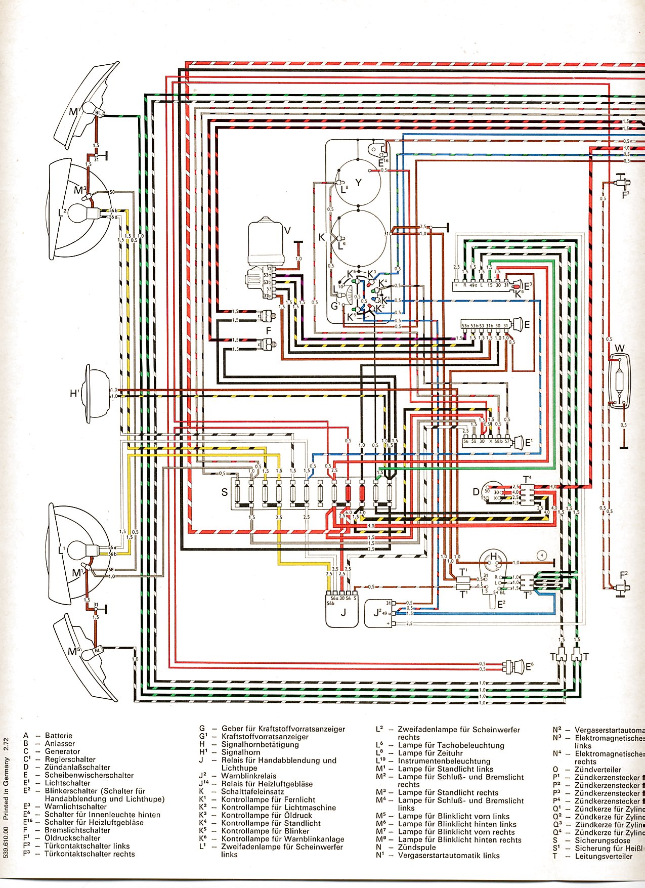
Blue Haynes, section 12.25 "Wiring Diagrams (page 12 of that section) = "Typical battery, starter, alternator".
These are fairly straight forward circuits that many of us are already familiar with, so might be easier to de-code.

Can we take the sw/ge (Black with yellow stripe) wire going down from the ignition switch ("D") (right near the centre of the page). Now I do know where it goes, but how do you get that information by looking at the number "90" shown in the little box ?

Re: Let's work together to try to understand Haynes circuits

Posted: 09 Mar 2013, 16:06
by itchyfeet
Page 12.19 Key to diagrams explains numbers in squares means : shows which track the wire is continued

if you look at the bottom of each diagram the 'track' numbers keep increasing from left to right, keep turning pages until you find 'track 90' which is on 12.33 then look up and you find sw/ge with a box that says 9 which is the 'track' you started with

I have spent quite a bit of time looking at them :D

next question?

Re: Let's work together to try to understand Haynes circuits

Posted: 09 Mar 2013, 16:07
by MidLifeCrisis
I like to think of those numbers in the square boxes as 'portals to another dimension' - in this case the other dimension is 'another page';

You need to find the page that has that number ('90' in this case) along the bottom of the page (below the 'ground' line). In this case the page is 12.33; trace your finger upwards from the number '90' on this new page until you find another square box which will magically have a number in it ('9' in this case) which corresponds with the number below the 'ground' line under the '90' square box on page 12.25. Quite clever really!!

This might help ..... (apologies for rubbish focus on pics but you get the idea)

Image

Re: Let's work together to try to understand Haynes circuits

Posted: 09 Mar 2013, 18:49
by AdrianC
<passes Bentley>

Re: Let's work together to try to understand Haynes circuits

Posted: 09 Mar 2013, 19:42
by scottbott
so it is not all double dutch,I wondered how they worked,thanks for explaining that

Re: Let's work together to try to understand Haynes circuits

Posted: 10 Mar 2013, 09:03
by CovKid
Its the lack of colour that makes them infuriating to use as you have to read that too. Oh how much easier it was with:

http://www.vintagebus.com/wiring/Type_2 ... 1971-1.jpg" onclick="window.open(this.href);return false;

Re: Let's work together to try to understand Haynes circuits

Posted: 10 Mar 2013, 09:57
by ghost123uk
CovKid wrote:Its the lack of colour that makes them infuriating to use as you have to read that too. Oh how much easier it was with: http://www.vintagebus.com/wiring" onclick="window.open(this.href);return false; [picture]

Aye but have you seen the length of some of those German words :shock:

Image


~~~~~~~~~~~~~~~~~~~~~~~~~~~~~~~~~~~~~~~~~~~~~~~~~~~~~~~~~~~~~~~~~~~~~~~~~~~~~~~~~~~~~~~~~~~~~~~~

Back on topic :roll:

itchyfeet wrote:Page 12.19 Key to diagrams explains numbers in squares means : shows which track the wire is continued, if you look at the bottom of each diagram the 'track' numbers keep increasing from left to right, keep turning pages until you find 'track 90' which is on 12.33 then look up and you find sw/ge with a box that says 9 which is the 'track' you started with

Ah, you see you and Mr / Ms MidLifeCrisis explained it well there, whereas the Page 12.19 Key to diagrams explains it not at all !!


itchyfeet wrote:next question?

OK, so continuing along the route of the Black yellow stripe wire on 12.33, it goes to the lighting switch (E1) then goes up the page via connector B10 on the relay plate to Relay J59. Our black/ yellow wire is live (when on) so it comes out of the relay (conx 1/85) it goes to "line 31" - Question = is this an earth rail on the relay plate (and if it is, how are we supposed to know ? The "key" page 12.19 doesn't tell us ! If it is an earth, then this relay is ON all the time as black / yellow is live, so why is it there at all ? You see this is typical of where the Haynes is unclear (well to me anyway).

Oh, and while we are there, what is relay J59 ? Haynes calls it "Relief relay for x contact" :? whatever the heck that is supposed to mean :shock: It would help I.D. what it does if I could figure out were the output wire, conx 3/87, at the bottom right of it in the diagram, had some info on where it went to ?

By the way, I do know what the relay is for, (it kills the headlights etc whilst cranking) but my point is that the Haynes diagram doesn't help anyone who doesn't already know :evil: (without the help of folks like "itchfeet" and "midlifecrisis").


I see the "8" in the black square by J59 is a test point for "The fault finding program" whatever that is :?

So J59 and associated wiring, reveal your secrets...

Re: Let's work together to try to understand Haynes circuits

Posted: 10 Mar 2013, 10:17
by Wychall

Re: Let's work together to try to understand Haynes circuits

Posted: 10 Mar 2013, 11:00
by ghost123uk
Wychall wrote:Does this document help at all?

http://www.bentleypublishers.com/images ... iagram.pdf

Or even more depth.........

http://dept.sfcollege.edu/InTech/AUTO/c ... agrams.pdf

Aye Brian, they would be useful to many folk. :ok

As I think I might have mentioned, I hardly ever need to use the diagrams for my own use, my background in electronics and a lifetime of doing car electrics too stand me in good stead ;) I figured that a topic on here to demystify the Haynes wiring diagrams would be a good resource and it has already helped :)

Re: Let's work together to try to understand Haynes circuits

Posted: 10 Mar 2013, 11:14
by itchyfeet
ghost123uk wrote:
itchyfeet wrote:next question?

OK, so continuing along the route of the Black yellow stripe wire on 12.33, it goes to the lighting switch (E1) then goes up the page via connector B10 on the relay plate to Relay J59. Our black/ yellow wire is live (when on) so it comes out of the relay (conx 1/85) it goes to "line 31" - Question = is this an earth rail on the relay plate (and if it is, how are we supposed to know ? The "key" page 12.19 doesn't tell us ! If it is an earth, then this relay is ON all the time as black / yellow is live, so why is it there at all ? You see this is typical of where the Haynes is unclear (well to me anyway).


you have to view all the pages joined together as one big long diagram, you would then see track 31in the relay plate/fuse box connects to ground on page 12.39

this realy in on with ignition stage 1 only, this can be seen by following to track 9 on page 12.25, look at the switch and it connects to the stage 1 contact , when the switch is on stage 2 ( cranking) it's disconnected. This switch is fed from track 30 in the realy plate, go to page 12.22 and you will see track 30 connecting to the battery.

got to go out now but will look at the other questions later :D
OK I'm back

I had a good look at haynes and decided that the output of the X relay must connect to the X track in the relay plate ( J59 is described as realy for X contact), the draftie who drew it must have poped out for a cuppa and forgotten to draw the line up to the X track. I then cheked Bentley and it is correct.

The X relay is as you say a realy to disconnect some devices when cranking, if you look at what connects from the X track it is only fog lighs and wipers

The "8" in the black square by J59 is not a test point its the realy number test points are in black circles, this is in the key on page 12.19

What Haynes fails to do is tell you what the relay numbers are and which connector is which on the back of the realy plate you need bentley for that.

Next?

Re: Let's work together to try to understand Haynes circuits

Posted: 10 Mar 2013, 21:34
by MidLifeCrisis
Haynes wiring diagrams always feel like the first draft done by some chap who mysteriously dropped dead the next day and his boss just assumed he'd finished the job and printed them out ......
..... I always assume they are correct until they simply do not make any rational sense, then head for Bentleys!!

Also FWIW - its 'Mr' MidLifeCrisis, my SO is stubbornly refusing to join me and continues as if she isn't over the hill!