Lots of work done on my van recently. Unfortunately it's not all documented on here in my Atlantic thread so lets rectify that

.
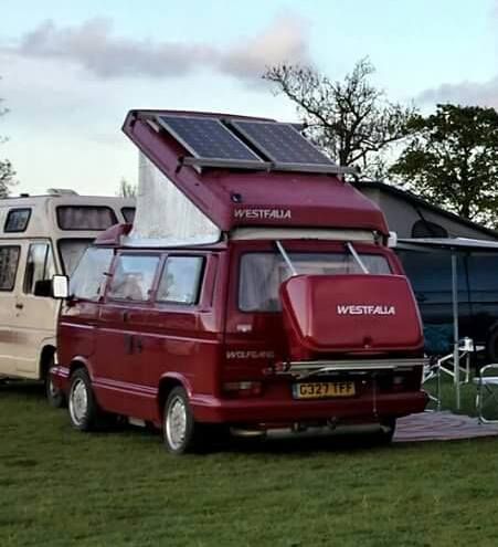
As your aware i managed to fit the solar panels to my roof rack. From there i've managed to get the install completed along with an extra leisure battery.
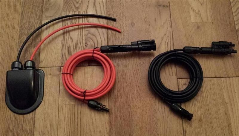
I sourced these from eBay along with a pair of adapters that would allow both panels to hook into a single feed.
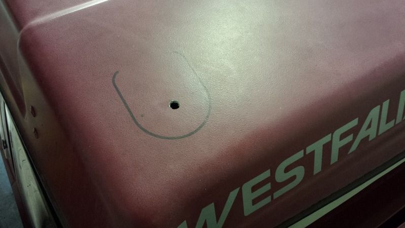
The next stage required drilling a hole in the pop top roof and mounting the cable entry gland with Sikaflex. I don’t make a habit of drilling holes in my van, but the way I looked at it was a hole drilled in the fiberglass pop top was far less intrusive than drilling a hole in the metal bodywork (which was an option I had seen done before). Each one achieves the same objective, and there is nothing to say that one way is right and the other wrong, but this is the route I decided to go down.
So I positioned and marked the gland on the roof for reference. Then drilled the hole.
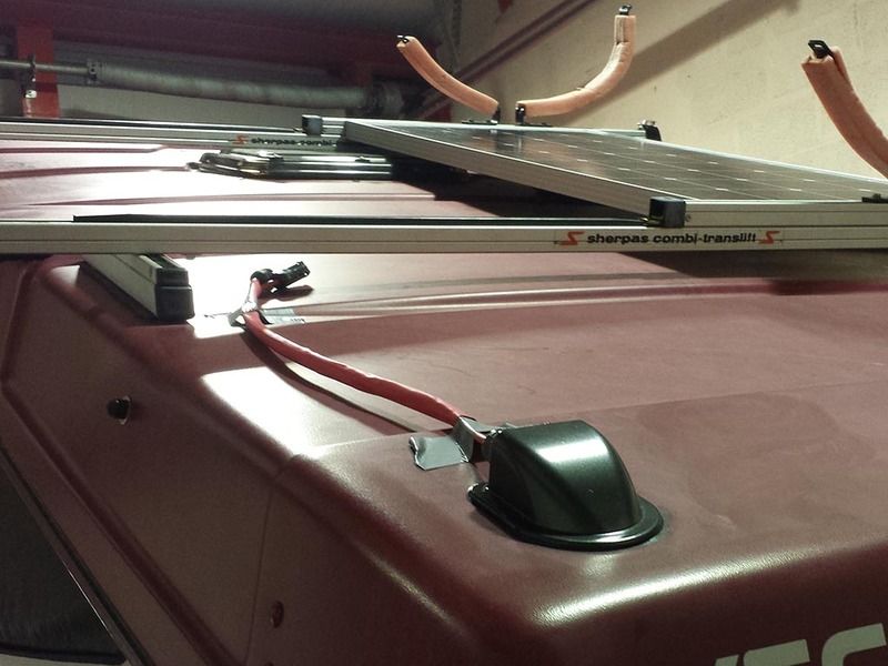
The entry gland was positioned after feeding the cables into the aperture. And Sikaflex was used to bond it to the roof. This was held in position for a couple of hours with tape to allow time for the bonding agent to go off enough that I felt i could remove it.
So the solar cables lay coiled up on the bed in the top bunk for a month or so before i started pushing forward with the internal cabling. First job was to try and establish the best route into the wardrobe. Then drill a hole (eeek!).
The cable drops into the top of the wardrobe area initially on the outside in between the rear window curtain. The com’s /data cable was just eased up along the rubber where the wardrobe front and the roof meet and follows the same path the solar cables take into the wardrobe.
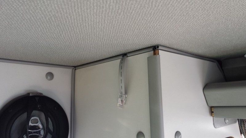
I made a small nick in the seal where it will rest and feed into the LCD display unit.
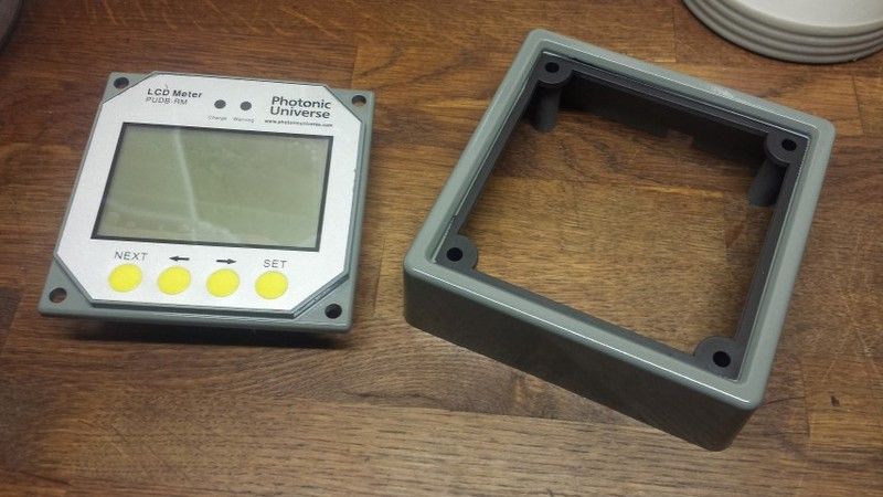
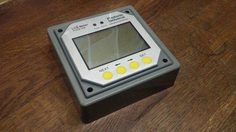
The unit itself came in black as pictured previously, so that’s been plastic primed and sprayed ‘industrial grey’ to more closely match the Westy interior.
Once the cables were fed into the wardrobe i needed to create a pathway to the location the solar controller would be sited. Since I decided solar would be a feature on my van I was looking constantly for information on how and where others had sited the components. The solar controller I had seen mounted in a multitude of places. These included
Inside the wardrobe – This would reduce space in an already narrow aperture and get in the way mounted higher up. Lower down this was not an option because this is used for the storage of shoes etc)
Outside the wardrobe underneath the LCD meter – This would look unsightly with all of the wires feeding into the controller and would be an unnecessary eyesore (IMO)
One particular location seemed better than any other. This was in one of the storage compartments next to the fridge underneath the rear table. It was deep enough that the controller would have enough room below it to accept the cables. So confident in my conviction that this was the place of all places, I set to drilling the two holes necessary to feed the cables and reach the unit. One hole was from the wardrobe to the first storage compartment above the water tank.
Feed from inside the wardrobe
Inside the first compartment
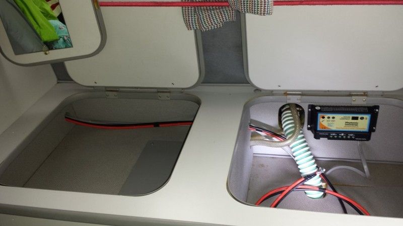
Feed into the second compartment next to fridge.
So once the cables were fed into the compartment the next thing was to mount the controller. I first placed the solar controller where i wanted it, marked the holes with a black pen and used a braddle to get the stainless self tappers to bite into the hardboard.
Solar controller mounted.
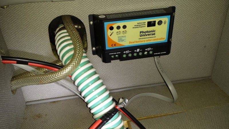
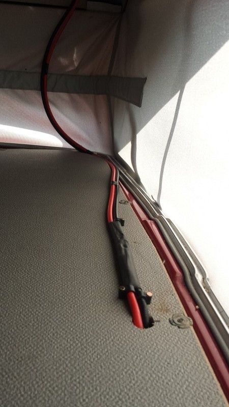
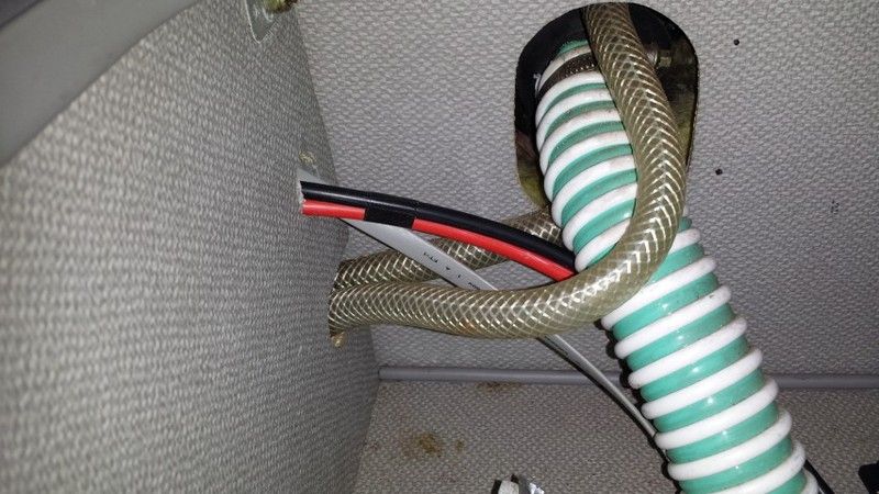
Here you can see the full run through to solar controller.
From wardrobe to cupboard
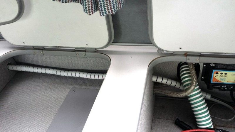
To neaten things up a little i have wrapped the cables in some cable tidy. I brought this from Maplin (UK) and was pretty pleased with the fact the colour is light grey. Far less obtrusive than black or white (although in the picture below it looks a little more obvious than it does in the flesh). The length was just right and i managed to feed all of the cables into the tidy and push it through the holes so it is one unbroken piece. It feeds all the way into the wardrobe and as far up as the outside of the wardrobe so a real neat job if i don’t say so myself.

Cables wrapped
Next I ran a two core cable from the controller to to leisure battery at the front. This was simply fed up through a gap in the unit and cable tied to the vent grid behind the cooker / draining board and sink. It then drops down into the cupboard.
Cable feed to leisure battery.
Below you can see the LCD display unit matched up in the location it will eventually sit. Not a perfect colour match but much better than the original black colour.
So the next thing to do was to wire everything together. I noticed that in the installation manual for the solar controller it states.
‘although the solar controller has built-in electronic protection, for safety and added protection please install inline fuses into the circuits between each battery and the controller, on the negative wire, as close to the batteries as possible. Current rating of fuses should be chosen according to the maximum power current / short circuit current of your solar panel’
I was a little confused because the printed installation / information manual that came with the controller also states that there should be a fuse fitted in the live from the solar panels also. So off I went to Maplin to get a couple of in line blade style fuse holders. I established that the rating of fuse i would use for both sides of the feeds would be 15amp. The short of each panel is just shy of 6amps so x 2 = 12 plus a little extra. I’m not an expert but my step dad (ex tv / radio engineer) confirmed this would be the rating i would need.
After a bit of wire stripping, soldering and heat shrink application I was all ready to connect everything. I had not gotten round to running the second battery cable to the diesel starter battery in the engine bay, but the dual battery controller will function quite happily with a single battery and does not have to have the second battery connected. Ultimately I want to get the starter battery connected. The charge from the controller can be split between the two batteries by percentage. I am thinking a 20% charge to the starter and the rest going to the leisure battery (house for those in the US) should work quite well for prolonged periods being static. This should maintain a few amps to keep enough charge in the starter battery to make sure we don’t get stuck, but the majority of the power will be diverted to the living area for TV, radio, phone / tablet charging and interior lights.
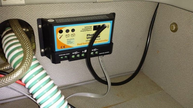
So here is the final install with the controller / LCD meter connected.
Controller Wired up
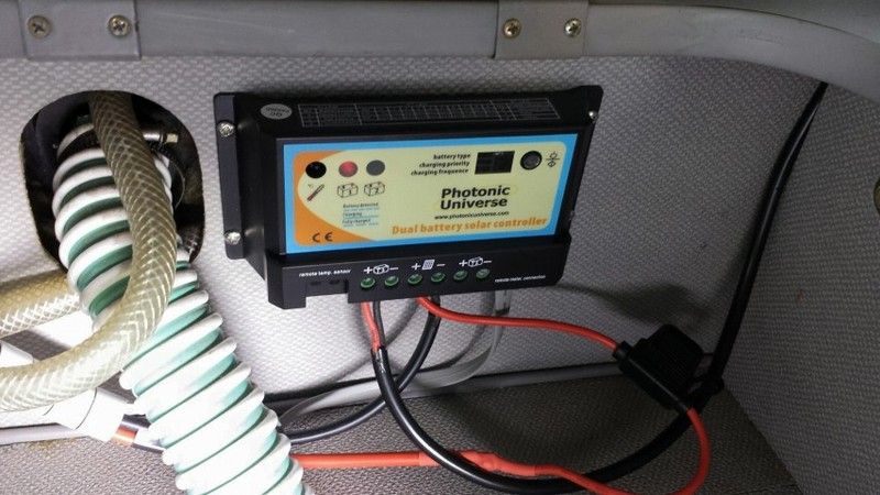
The only setting I had to change on the solar controller was to the battery type which should be set to Type 3 for ‘Flooded’ (Lead acid) battery. The other options are AMG and sealed (I think?).
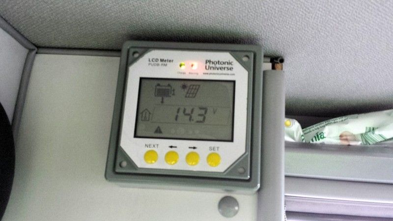
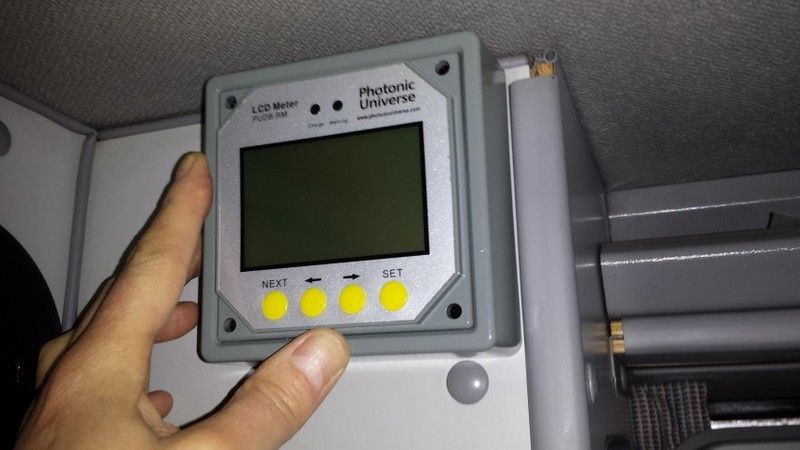
Here you can see the LCD controller connected. I fixed it to the wardrobe unit using double sided foam pads. Having fed the data cable over the wardrobe top the flat cable was very tight and forced the face front out and away from the units. The low profile of double sided tape would have made everything tight and probably wouldn’t have given the extra couple of mm required to mount. However, the double sided foam allowed that extra distance to mount. It does tend to rock a fraction when the buttons are pressed as the foam gives a little, but this is livable and far better than drilling and self tapping the display into the wardrobe unit. I’ts pretty secure and certainly isn’t going anywhere in a hurry. Also, it’s a novelty now so I am having a play and seeing what does what, but I am sure I will settle on a particular screen that will give me the information I feel most appropriate and leave it set to that….in time
You can see two lights on the display. One is green showing that the panels are charging
, the second is red showing a warning

. The annoying thing is that the warning is just to show that the second battery isn’t attached. As said previously the controller functions perfectly well without a second battery, but there is no way of acknowledging you are happy with one battery to remove the warning. Anyways, all in all I have a working system so win, win
UPDATE
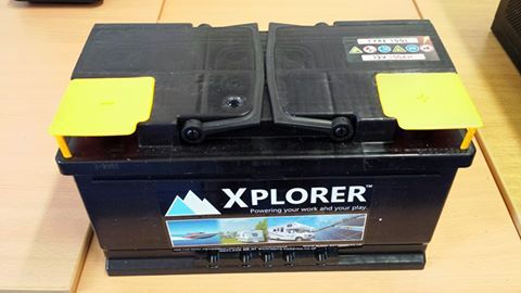
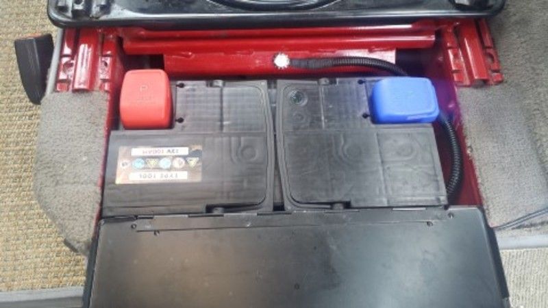
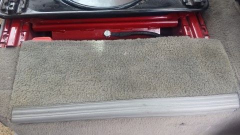
It seemed a shame to have all of this available power, yet only a single leisure battery to save it to. So my next job was to source a suitable battery that would fit in the compartment behind the right hand (passenger) seat. This would be linked directly to the first battery giving a larger source of power to draw from. The one I chose was advertised as a T25 battery on ebay and is branded Xplorer. The seller is alpha_man_batteries. This battery combined with my existing would give me a total of 180ah
I decided I would get this done by an auto electrician as it would involve feeding cables under the van and i preferred it to be done correctly. I did mention to him that if he had time that he try and route a cable from the solar controller to the starter battery in the engine compartment. I had quite recently been made aware that the interior lights run off this battery and i was mindful that this would reduce the chance of finding myself in a position where i could not start my van should too much power be used. It was at this point I also made the decision to change my fluorescent interior light for LED (Guide here LED interior light upgrade)
After two days I collected my van and was really happy with the work he had done fitting the leisure battery. As an added bonus he had managed to route the cable from controller to starter battery. This is the leisure battery. As you can see it’s snug but not not too obvious when the compartment door is closed.
Battery
Door only slightly proud
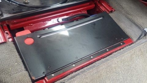
Door only slightly proud
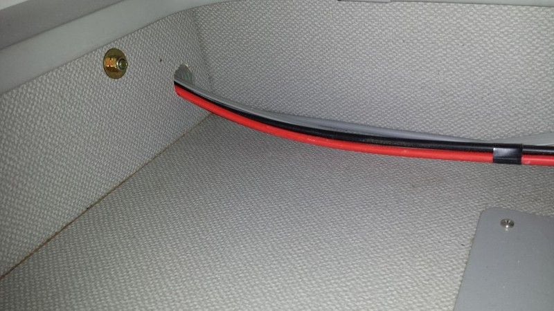
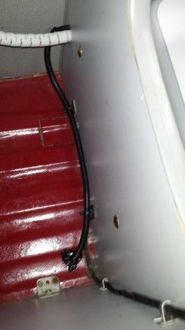
Here you can see where the black cable for the starter battery enters the wardrobe (right) , and feeds through a hole he drilled in the floor, which in turn is fed into the engine bay and round to the battery. The hole was sikaflexed to stop water ingress.
Routing of cable in wardrobe from solar controller to battery
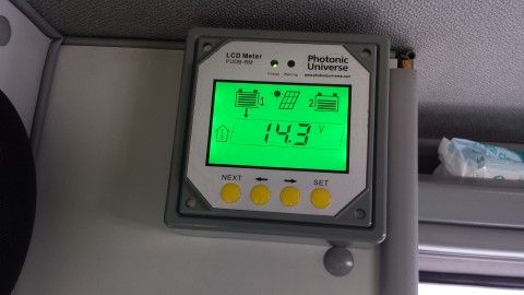
Below you can see that the LED solar display is now showing two batteries connected and the red error / warning light has gone out
Well that’s pretty much my solar install. All of this can be found on my webpage
http://www.daswolfgang.com" onclick="window.open(this.href);return false;
Andy


van's looking good. Where you heading in the van?


