Page 4 of 11
Re: Fuel Gauge/Sender Variants
Posted: 25 Jul 2018, 19:22
by CJH
bigbadbob76 wrote:one answer to the two different senders for the same gauge is if there was an extra resistor on the early PCB in parallel with the sender.
Anyone found one?
Wouldn't that have to be for the later PCB - to take the lower maximum (168) towards the same value as the early sender's maximum (288)? But that would then mean there'd be a problem at the 'full' end - the resistance could never get low enough for the gauge to register full.
Re: Fuel Gauge/Sender Variants
Posted: 25 Jul 2018, 19:29
by bigbadbob76
It's the other way around, putting a resistor in parallel with the 288 would lower it to closer to 168 at the empty end and that would be a high enough resistance to not effect the full value much.
I've done the maths for 5.6v zener/120 ohm/500 ohm.
if you use two 120 ohm resistors in series you'll be fine.
The damping circuit will need work once we get the basics working.
The capacitor might be quite big.

Re: Fuel Gauge/Sender Variants
Posted: 25 Jul 2018, 19:36
by CJH
bigbadbob76 wrote:It's the other way around, putting a resistor in parallel with the 288 would lower it to closer to 168 at the empty end and that would be a high enough resistance to not effect the full value much.
Oops - missed that bit!
bigbadbob76 wrote:
I've done the maths for 5.6v zener/120 ohm/500 ohm.
The transistor base emitter current would be 30mA at 10V and 11mA at 7.66V which is a bit high for a gp transistor.
What transistors have you got handy?
I'll have a rummage and see what I've got.
Re: Fuel Gauge/Sender Variants
Posted: 25 Jul 2018, 19:58
by bigbadbob76
I edited my post to say use 2 x 120 ohm in series, me bad, shouldn't E D I T.

Still worth knowing what transistors you have though.

Re: Fuel Gauge/Sender Variants
Posted: 25 Jul 2018, 20:01
by CJH
bigbadbob76 wrote:I edited my post to say use 2 x 120 ohm in series, me bad, shouldn't E D I T.
Still worth knowing what transistors you have though.
Spotted that - I've got some 2N2222A and some 2N3904BU.
[quote="bigbadbob76"
I've done the maths for 5.6v zener/120 ohm/500 ohm.
if you use two 120 ohm resistors in series you'll be fine.
The damping circuit will need work once we get the basics working.
The capacitor might be quite big.
[/quote]
Good stuff.
Is it the zener that is the issue needing two 120 ohm resistors in series? I assumed that (110 + up-to-470) would be covered by (120 + up-to-500). If the zener is the issue I'll quite happily get some 6.8V items in.
Re: Fuel Gauge/Sender Variants
Posted: 25 Jul 2018, 21:36
by bigbadbob76
2N2222 is a good choice.

Yes, the 5.6v zener means you need to drop more volts accross R1 so it has to be greater resistance.
240 ohms will be fine for testing on veroboard with the 5.6 zener.
The final production version might get a 6.8 zener.
Re: Fuel Gauge/Sender Variants
Posted: 26 Jul 2018, 07:55
by CJH
Great, ok, so I can experiment with the bits I've got (or will have) to hand.
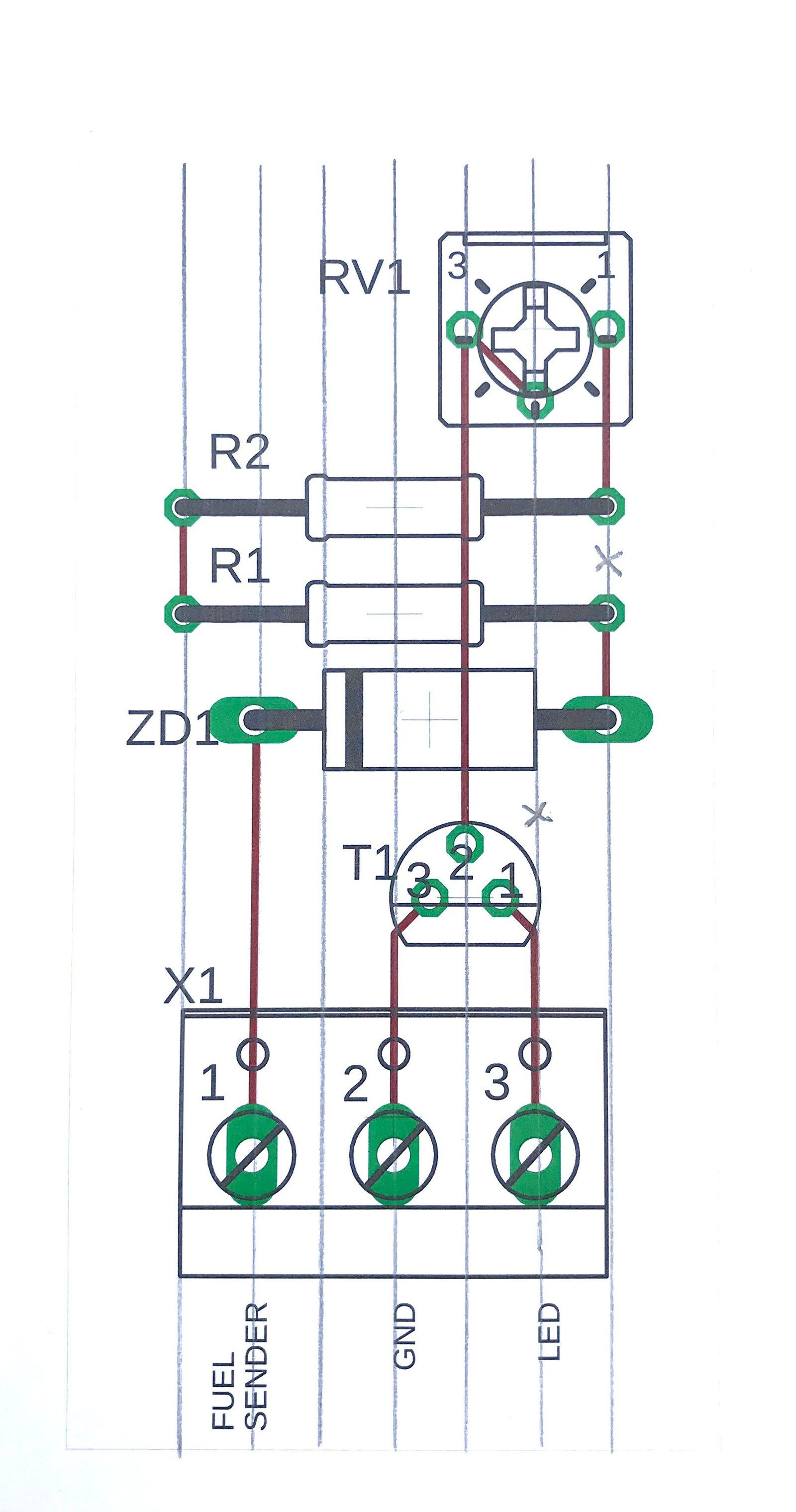
I've made a layout that will suit a piece of stripboard:
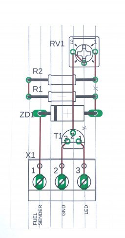
I'll probably start putting this together this evening (although first priority is to adjust the rear brakes so the handbrake gets through tomorrow's MOT) - the potentiometer and zener diode are in a package that left Shenzen yesterday - currently in flight from Hong Kong, so should be with me by the weekend.
Re: Fuel Gauge/Sender Variants
Posted: 26 Jul 2018, 11:19
by CJH
For testing purposes, presumably I can connect the sender line to my bench supply, set the supply voltage to around 7.5V, and then adjust RV1 until the LED and GND terminals connect and disconnect as the supply voltage is adjusted up and down through 7.66V (corresponding to 160 ohms on the sender).
Re: Fuel Gauge/Sender Variants
Posted: 26 Jul 2018, 17:04
by bigbadbob76
Yes, you could test like that but having the led and resistor would be better as you then get a feel for the point when the led comes on.
It's an analogue circuit so nothing switches at a defined point.
ideally you should connect your 160 ohm resistors as the sender, connect the gauge and supply both the led and the gauge from the 10V supply.
Start with RV1 fully clockwise and turn it back until the led comes on.
Then try other sender resistances.
My PCB kit came today, cheers Chris, I'll get populating it.
The 3d led holders look really snazzy.
Re: Fuel Gauge/Sender Variants
Posted: 26 Jul 2018, 17:30
by CJH
bigbadbob76 wrote:Yes, you could test like that but having the led and resistor would be better as you then get a feel for the point when the led comes on.
Ok, am I missing something? I assumed that having a continuity tester across the collector and emitter will tell me the point at which the LED would come on. Will that be different if the LED is actually in the circuit?
bigbadbob76 wrote:My PCB kit came today, cheers Chris, I'll get populating it.
The 3d led holders look really snazzy.
Good stuff - will be good to get your feedback as you're evidently a lot more experienced at this than me.
Re: Fuel Gauge/Sender Variants
Posted: 26 Jul 2018, 18:12
by bigbadbob76
The transistor is not an on/off switch, it's like a proportional valve.
The base-emitter current controls the valve, more base-emitter current= more collector-emitter current up to the saturation point when it's fully on.
Your continuity tester won't be supplying the same collector current as the led circuit so it won't give a true reading of LED on status.
In a digital circuit where you are using either 0v or 5v it would act as a switch as 5v would saturate the base but in our case where we have a varying voltage it becomes less predicatable depending on exact values of components so it's easier to adjust VR1 and suck it and see.
I don't want to get into the realms of calculating current gain for the transistor when you can do it on the bench.
Aye, I've been in this game professionally for over 22 years and as a student/hobbyist before that, glad to know the brain still works.

What it does mean is that I know when to buy your kit and save myself doing all the hard work so I'll gladly give you feedback and glad to help you with this circuit too.
If my tacho and gauges get here soon I might build the circuit myself and have a play with it, seems wierd doing it remotely like this when I'm used to trying things out on the bench. I'm a hands on kind of guy rathar than a theorist. Now where did I leave my zener diodes......
Re: Fuel Gauge/Sender Variants
Posted: 26 Jul 2018, 19:40
by CJH
bigbadbob76 wrote:The transistor is not an on/off switch, it's like a proportional valve.
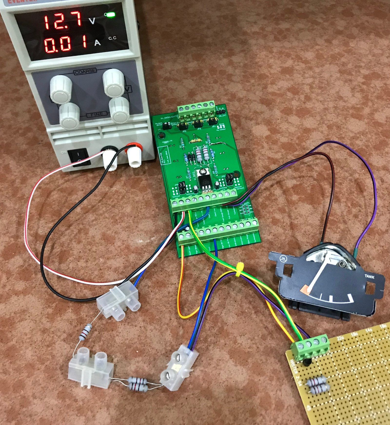
Ah, got it. Ok, so I've rigged up a full dashboard simulation using an old battle-scarred dash PCB. This is with 180 ohms in the sender circuit. The red/yellow wire goes to the LED6 terminal, which is configured as 'switched -ve', and which has an orange 2V LED and a 2k2 current limiting resistor.
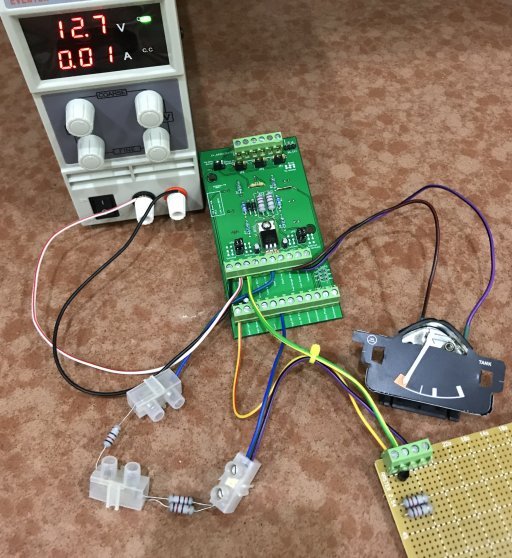
The stripboard is still waiting for the zener diode and the potentiometer to arrive - tomorrow with a bit of luck, since the package is now in flight between Leipzig and East Midlands
Re: Fuel Gauge/Sender Variants
Posted: 26 Jul 2018, 21:40
by bigbadbob76
Looking good Chris.
What zener's are coming? 5.6's?
Re: Fuel Gauge/Sender Variants
Posted: 27 Jul 2018, 05:43
by morr
CJH wrote:
Given that the part number for the gauges didn't change when the senders changed, one thing that seems odd about these results is that the newer sender will never generate a resistance high enough to put the needle this far into the red - it only goes up to 168 ohms apparently. That doesn't seem right. I'll bet people with late vans have seen their needles further into the red than this.
Could this be that whilst the part number for the gauge didn't change, its calibration did, using the 2 holes in the rear of the gauge you can alter the endpoints of the needles sweep.
I've been putting together a resistance box to emulate the vw tool and the following are the resistance values I garnered online for all fuel gauges (includes T25, Golf 1 & 2, possibly more) from a few sources.
+/- Ohms
full 2 34
1/4 2 116
empty 3 168
reserve 3 184
empty 3 284
Re: Fuel Gauge/Sender Variants
Posted: 27 Jul 2018, 06:16
by 937carrera
That's good to know, especially about the calibration adjusters.
You can just do the conversion with maths:
https://www.s2forum.com/forum/technical ... e-checking
VW1301 value * 0.5013 + 9.367 = resistance in ohms, and
(Resistance in ohms - 9.367 ) / 0.5013 = VW1301 value
simplifying:
VW1301 value / 2 + 10 = ohms
Ohms * 2 - 20 = VW 1301