Page 3 of 11
Re: Dashboard PCB Replacement (CJH Design)
Posted: 21 Jun 2025, 18:09
by TwinTurbo
Length and width don't matter. the board can be shrunk a bit and some of the screw terminals replaced with smaller connectors. the likes of the voltage regulation could be moved to the edge card too.
The only dimensions needed are the placement of the LED centers from one of the mounting holes.
It would be good to make a PCB for the gauge cluster itsellf rather than lots of indivdualy sprawling wire. but I don't have the dimensions of the guage pin layout.
Cheers
Rob
Re: Dashboard PCB Replacement (CJH Design)
Posted: 21 Jun 2025, 18:21
by icosahedron
Main board: 65 x 123 mm
Connector: 65 x 24 mm
Re: Dashboard PCB Replacement (CJH Design)
Posted: 21 Jun 2025, 18:51
by The Hairy Camper
TwinTurbo wrote: ↑21 Jun 2025, 18:09
Length and width don't matter. the board can be shrunk a bit and some of the screw terminals replaced with smaller connectors. the likes of the voltage regulation could be moved to the edge card too.
The only dimensions needed are the placement of the LED centers from one of the mounting holes.
It would be good to make a PCB for the gauge cluster itsellf rather than lots of indivdualy sprawling wire. but I don't have the dimensions of the guage pin layout.
Cheers
Rob
I understand what you mean, Rob. LED position and mounting holes are the most important. Within reason though I suppose, I don't think their is much room to expand when you look at CJH's PCB mounted on the dash.
I think if you wanted more PCB boards for Clock, tachometer etc, you would probably need to go back a ribbon based PCB. Space behind the dash is limited, if wires can do the job well enough I'd probably stick with them. You won't see them once they're installed.
Re: Dashboard PCB Replacement (CJH Design)
Posted: 21 Jun 2025, 21:48
by icosahedron
Here are measurements for the LED positions in inches:

Re: Dashboard PCB Replacement (CJH Design)
Posted: 21 Jun 2025, 22:08
by The Hairy Camper
Nice work icosahedron. That looks really useful
Re: Dashboard PCB Replacement (CJH Design)
Posted: 21 Jun 2025, 23:33
by TwinTurbo
thanks , that is mega useful.
Rob
Re: Dashboard PCB Replacement (CJH Design)
Posted: 22 Jun 2025, 13:44
by TwinTurbo
Ok converted to offset from lower hole "Datum, lower 3.5mm pad 0.0"
column1 .3" =.762*10 =
7.62
column2 2.1 = 5.334*10 53.34 /2 =
26.67
column3 1.8 = 4.572*10
45.72
column4 2.1 = 5.334*10
53.34
Row1 .25 = 0.635*10
6.35
Row2 .8125 = 2.06375*10
10.6375
Row3 .1375 = 3.4925*10
34.925
Row4 1.6 = 4.064*10
40.64
Row5 1.8 = 4.572*x10
45.72
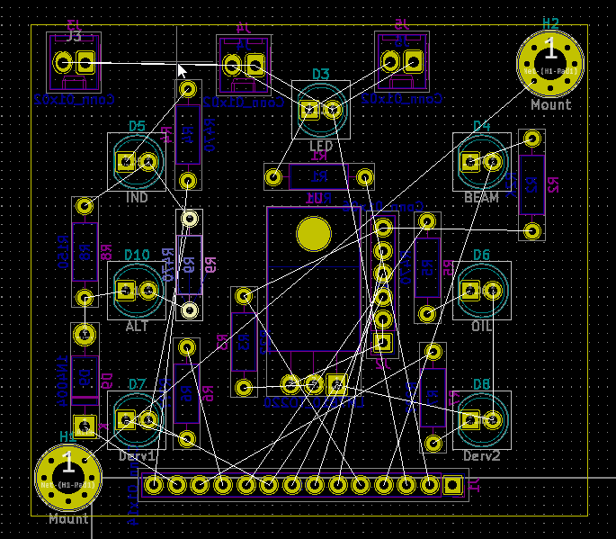
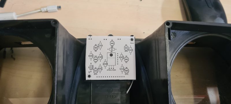
Basic schematic
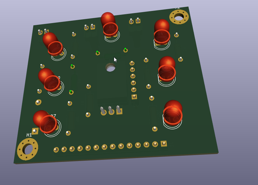
Frontside of board
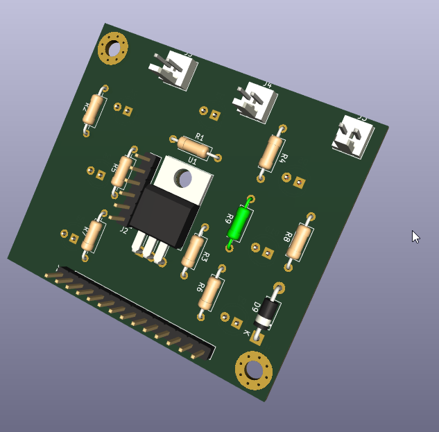
Backside of board.
And the general size for guidance. ( Flipped over )
https://www.twistedpear.org.uk/wp-conte ... 826417.jpg
Re: Dashboard PCB Replacement (CJH Design)
Posted: 22 Jun 2025, 13:48
by TwinTurbo
This is a rough V0.0.1 which will be sent to be printed to confirm mechanical fitment whilst futher development of the circuit continues.
I have used molex 254's connectors for the illumination.
The pin headers for the 14 pin ( to the edge connector ) and 6 pin to the guages. Are just to get something on the board , may well be replaced.
Re: Dashboard PCB Replacement (CJH Design)
Posted: 22 Jun 2025, 18:20
by The Hairy Camper
Very impressive work Rob. Are you going for the multiple PCB board design then? You've made a lot more progress than me.


Re: Dashboard PCB Replacement (CJH Design)
Posted: 22 Jun 2025, 19:18
by TwinTurbo
Undecided on the route at present Will probbaly stick with the original overall design.
I spent the afternoon transposing the PCB photos into the full schematic.
I need to go and populate all the component values and correct a few footprints but it's essentialy not far off.
Need to look at the edge connector board too.
Re: Dashboard PCB Replacement (CJH Design)
Posted: 22 Jun 2025, 19:41
by The Hairy Camper
I think I would like to stick with the shape that CJH used. We know it fits and he had good feedback.
If you go in a different direction it will be interesting to see your final design.
How long do you think it will be before you have a prototype? The company I was talking too said it should take them 2 weeks to make the files if I can give them the measurements. I have the main PCB board measurements, and I'll hopefully finish the multiplug measurements tonight.
Re: Dashboard PCB Replacement (CJH Design)
Posted: 22 Jun 2025, 19:45
by TwinTurbo
It will take a coul e of weeks for the first PCB to turn up to verify the mechanical fit. And I will be on with the edge connector and finalising the mainboard during that time. So maybe a month to a full proto.
Re: Dashboard PCB Replacement (CJH Design)
Posted: 22 Jun 2025, 20:47
by BarnyE
https://ebay.us/m/PfO3L2
I’ve seen these on eBay, are they what you’re looking for?
Sent from my iPhone using Tapatalk
Re: Dashboard PCB Replacement (CJH Design)
Posted: 23 Jun 2025, 04:02
by TwinTurbo
layzy design at a premium prioce. just look at the warning LED's that are on flying leads.
Re: Dashboard PCB Replacement (CJH Design)
Posted: 23 Jun 2025, 18:21
by TwinTurbo
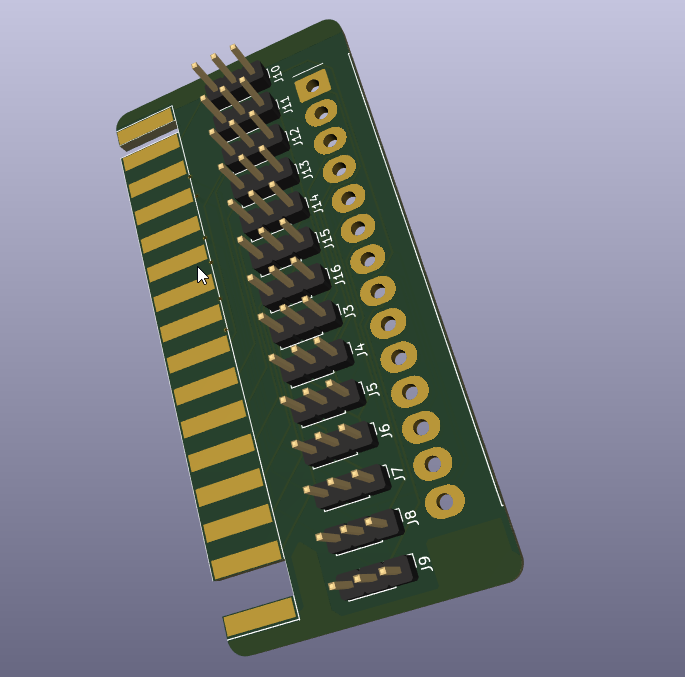
Edge connector board to accept a 3.96" Pitch Molex connector. Will print to paper and check it fits.