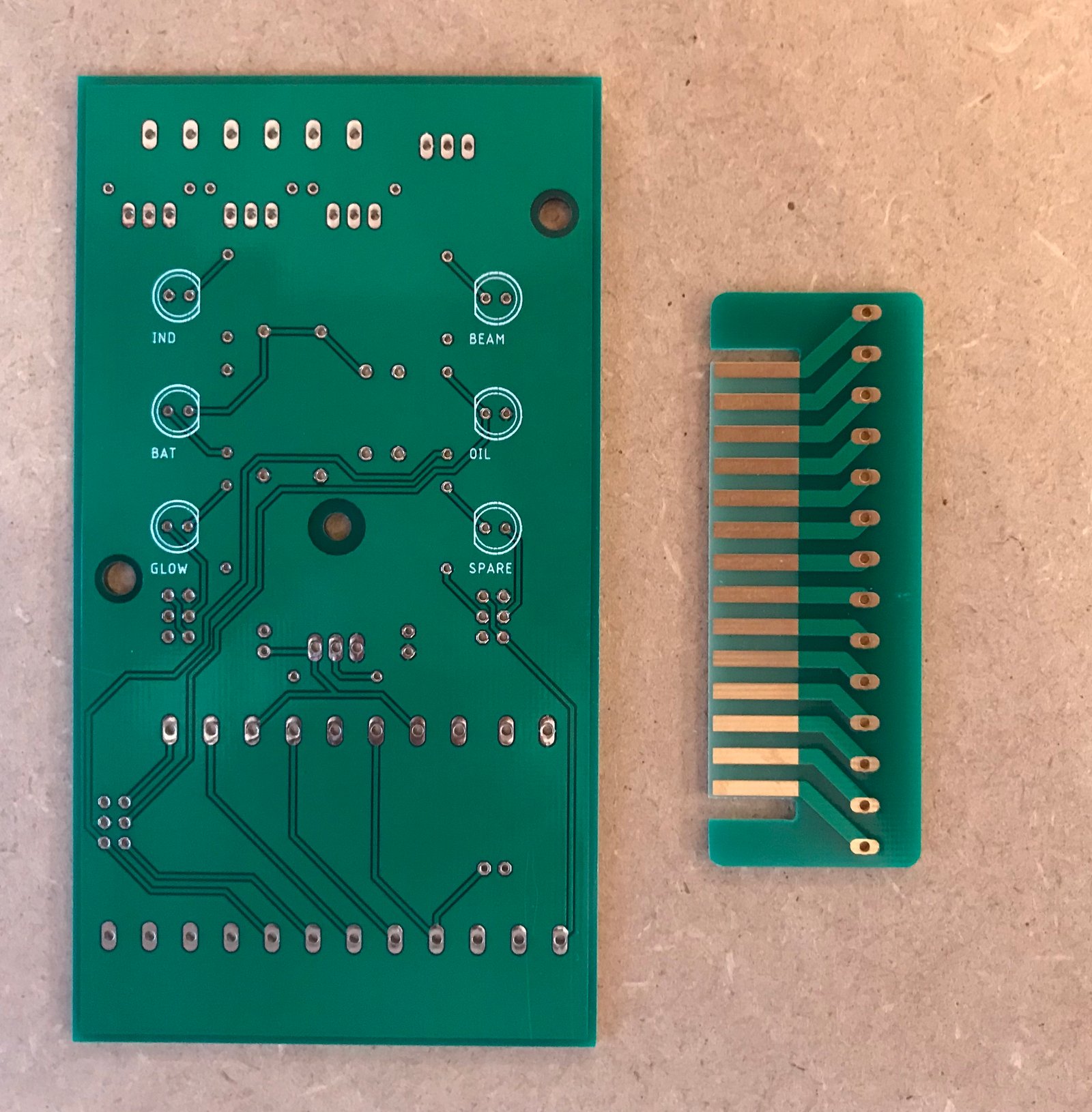
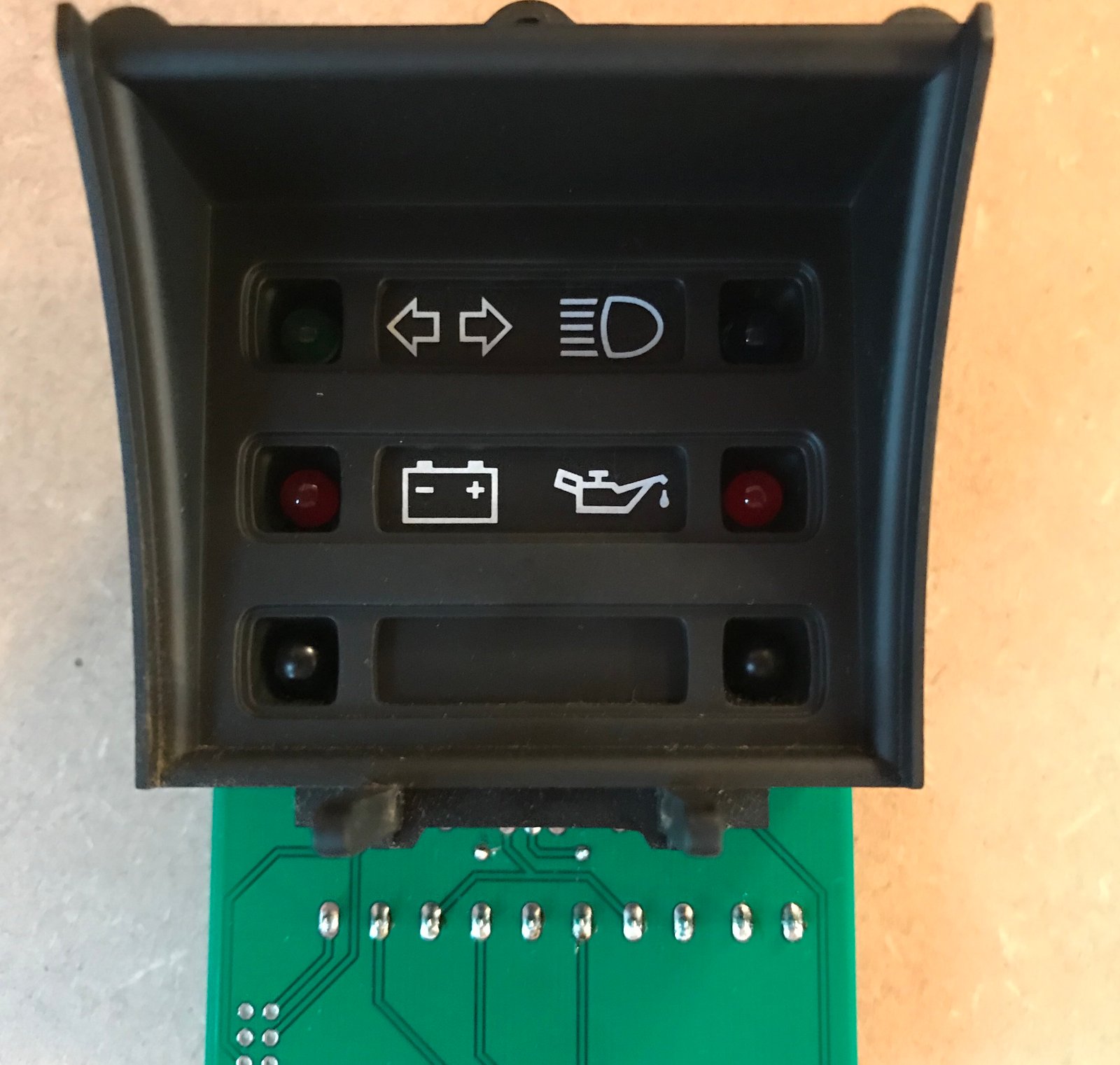
Yes, certainly, anyone who's already implemented an alternative to the factory multiplug should still be able to connect up to the LED board, and will have no need of the 'fingers' multiplug adapter. And in terms of additional connections, I've tried to make the inputs to the LED board a superset of everything on any of the different dash configurations (so the same board should work for all models), plus there's an extra input to run a 6th LED if you have something else you need a dash warning light for.
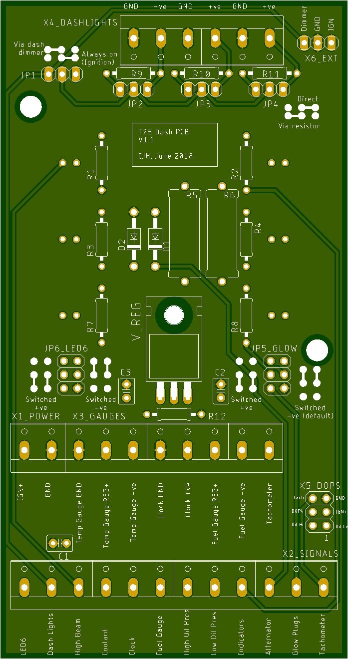
One of my aims is to make this flexible, so there aren't separate PCBs for diesel/petrol, early/late etc. But I've only got an early petrol dash (with a retro-fitted time clock), so I can't be certain that I've covered all the options - I'm open to suggestions for the next iteration.
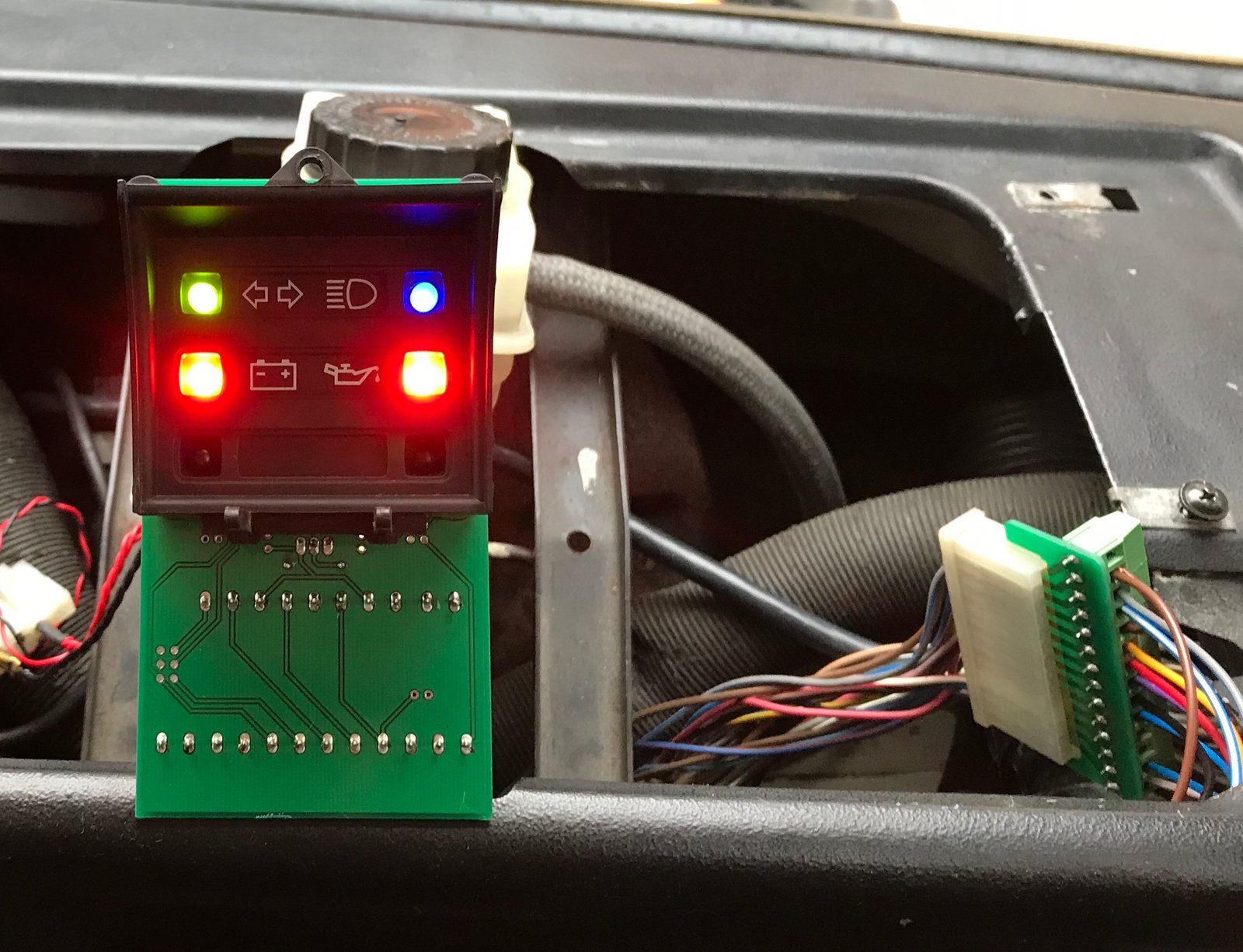
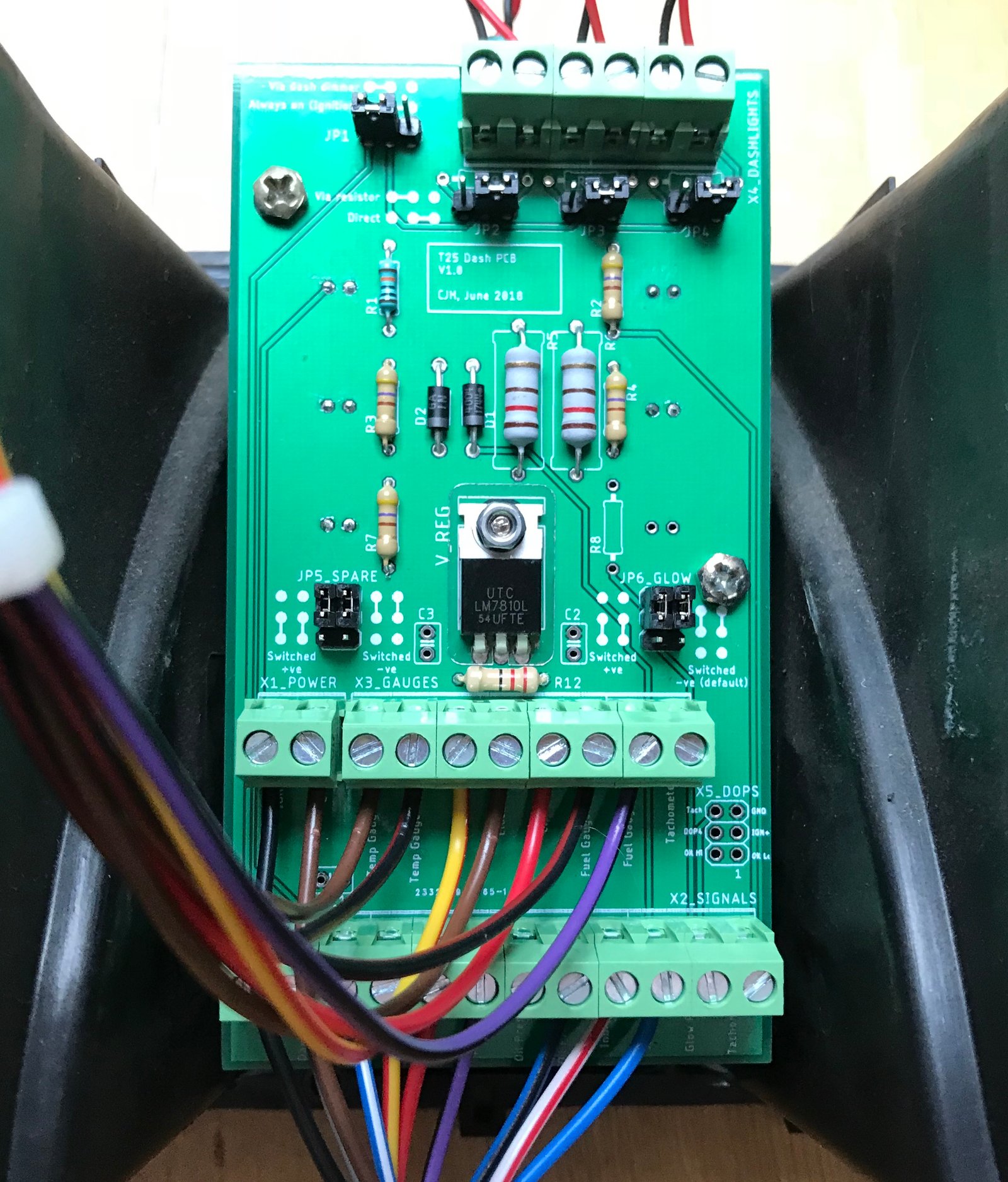
I've finished building mine up this morning. Some more photos.
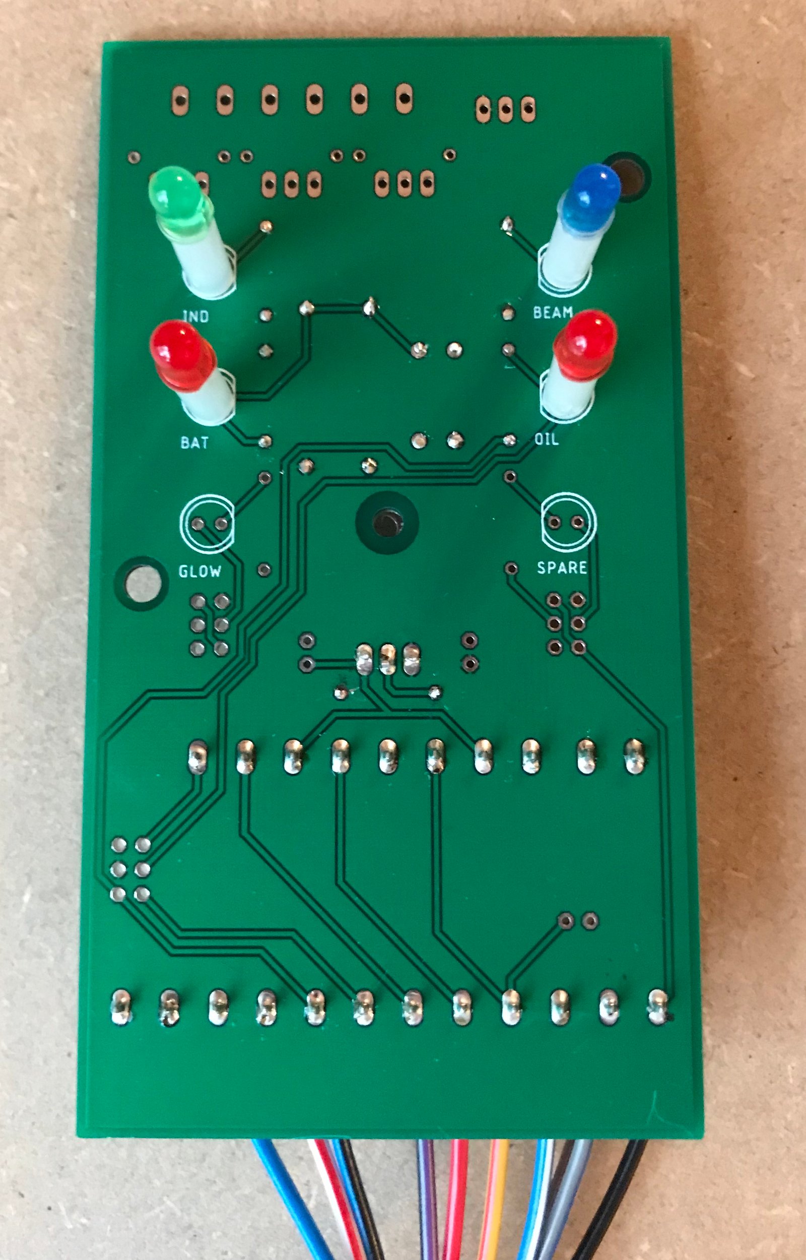
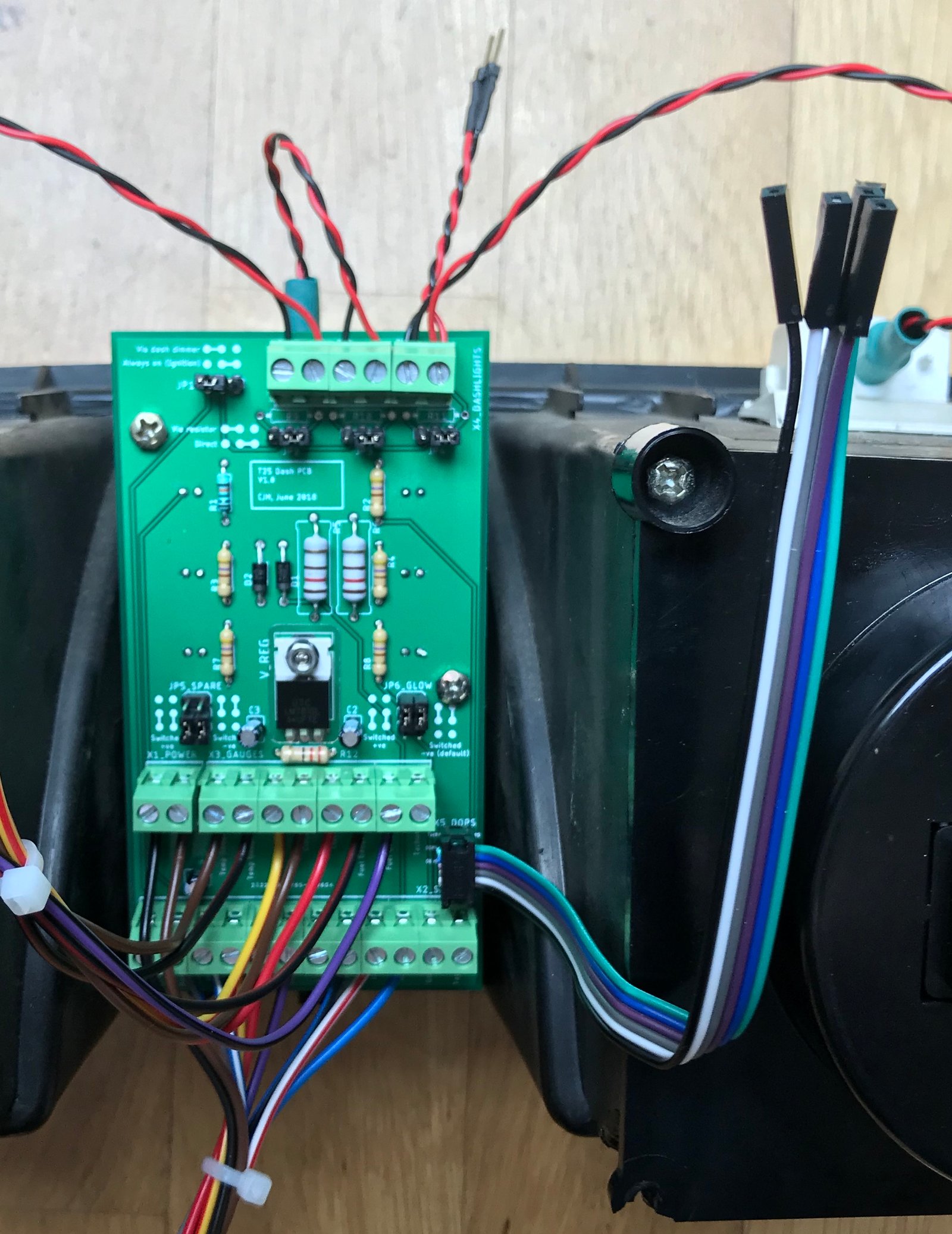
Here's an overview. I've used dimmable 0.2W LEDs as the dash illumination bulbs. I struggled to find a suitable wired bulb socket, so in the end I bought standard replacement bulbs and soldered wires onto the terminals.
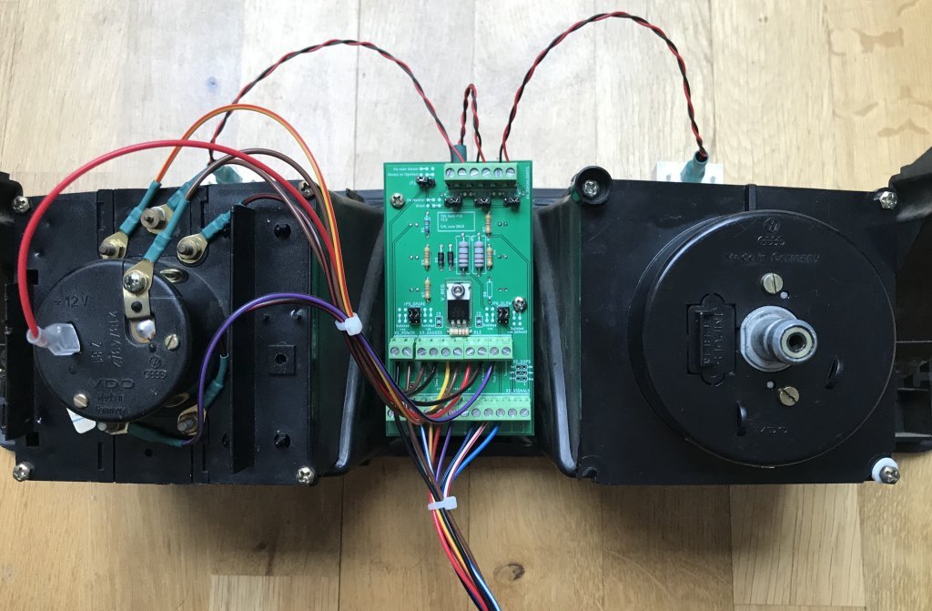
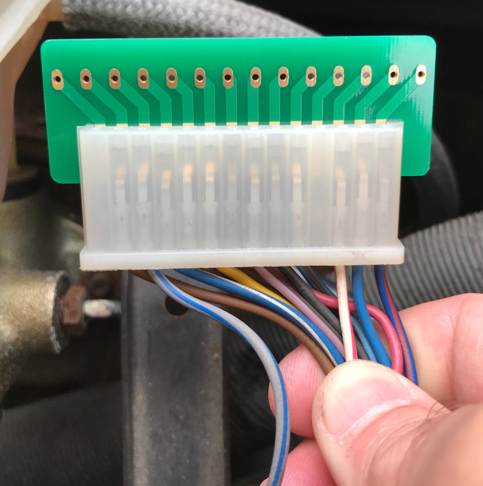
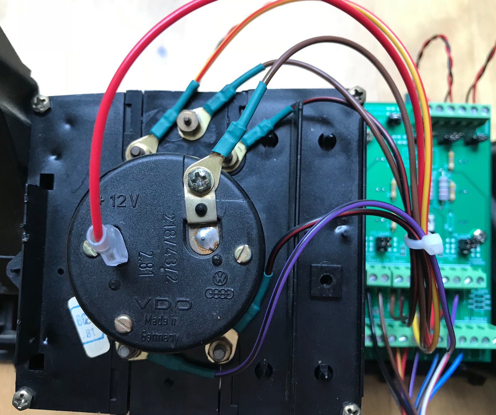
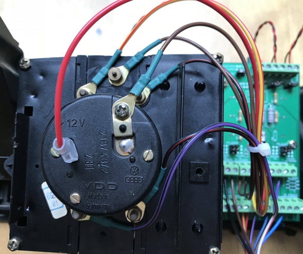
Here's the gauges wiring. There is no 'standard' set of wire colours for these, because the original flexible circuit board didn't use wires, but I stuck to the colours used for the corresponding connections on the multiplug, and added black/red as my 'regulated 10V' colour.
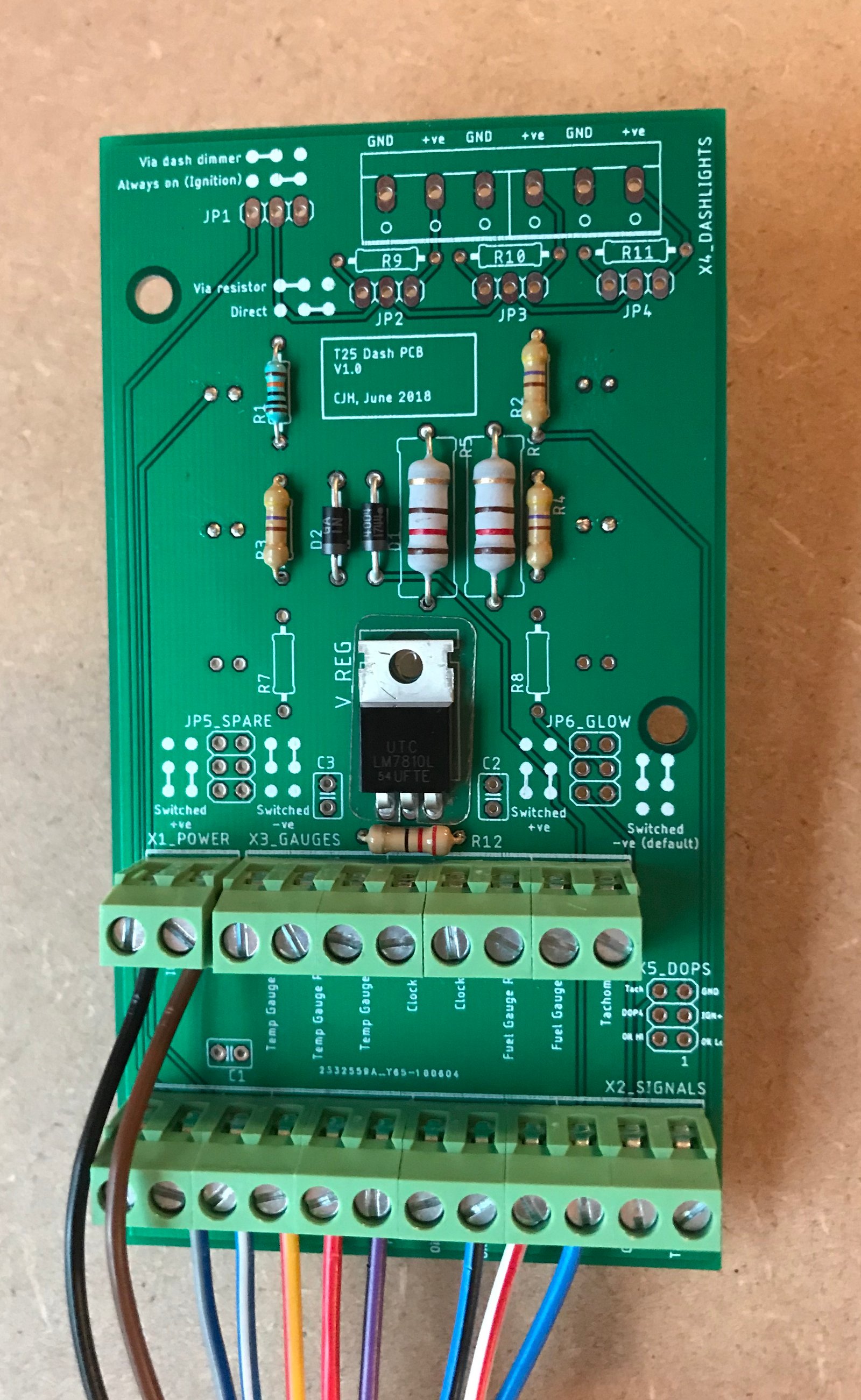
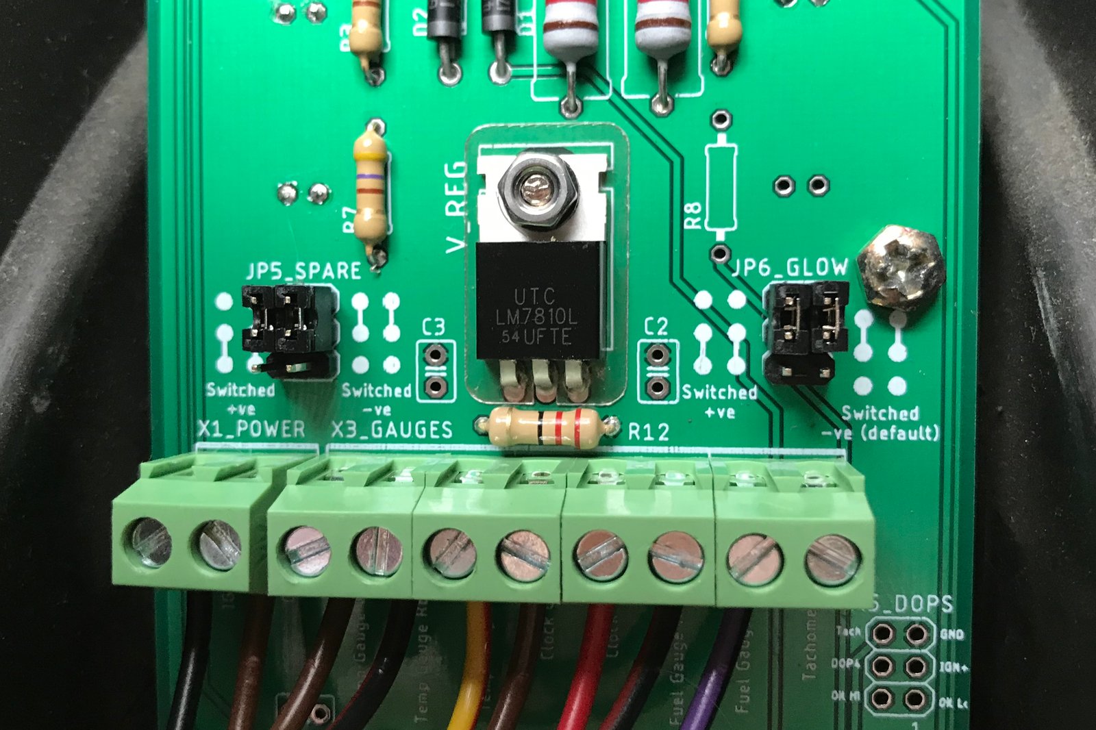
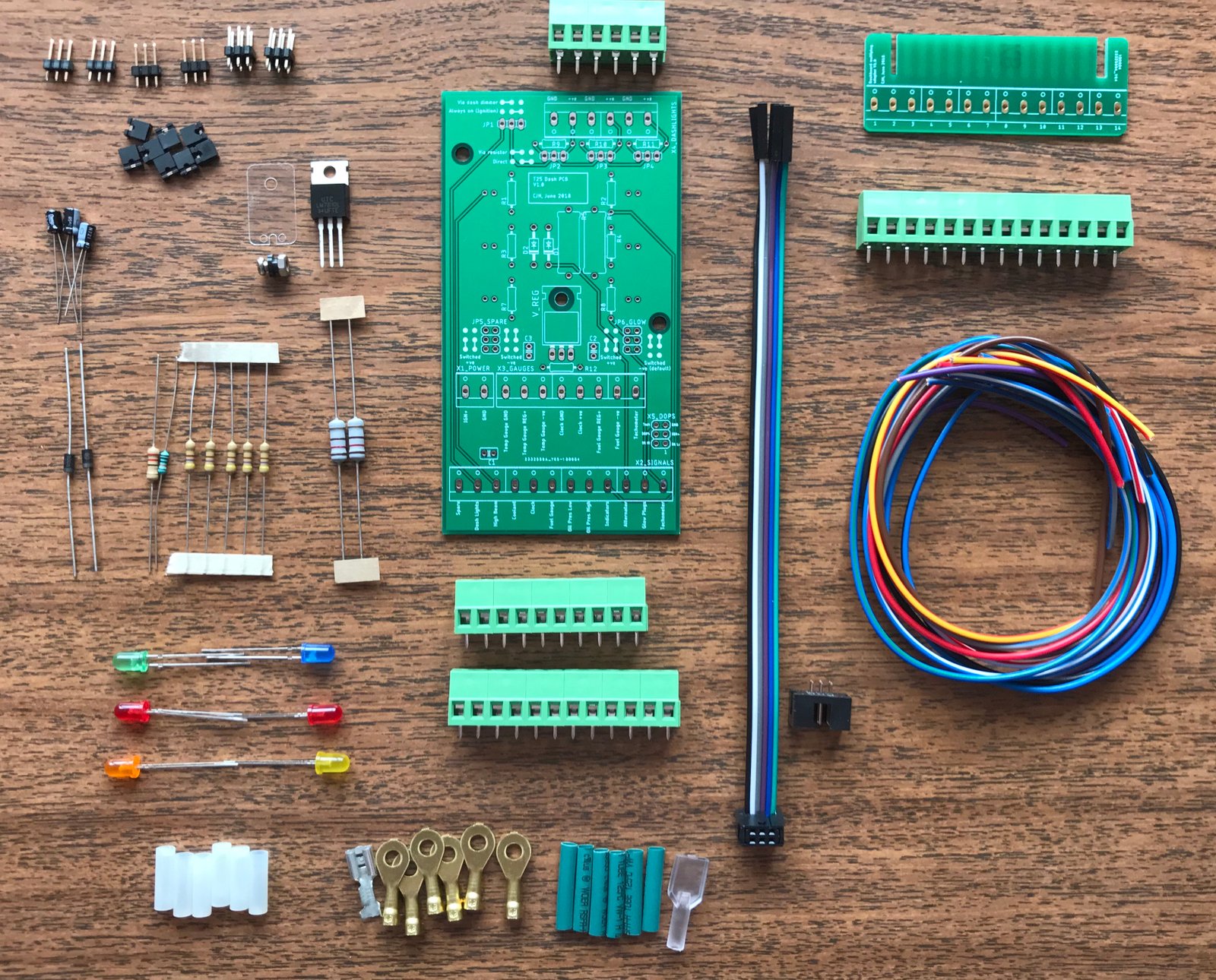
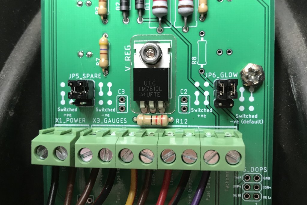
Here's the built-up PCB. I put a yellow LED in the 6th (unused) dash slot so I could test the jumper options. Since I have a petrol dash I could have used the glowplugs LED slot as a spare as well, but I'm struggling to think of a use for one spare, never mind two. I haven't yet fitted any of the capacitors - one is for the clock supply (not present on my original 'early' flexible circuit board I believe) and the other two are to provide 'optimum stability' for the 10V regulated supply. I'll see how the dash behaves for a while then fit the capacitors and see if anything changes.
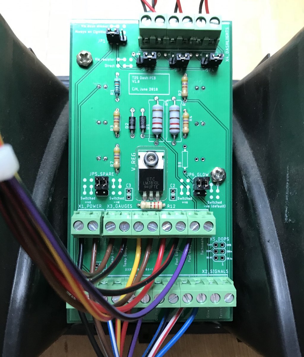
Here's a close-up of the jumpers for the glowplugs and 'spare' LEDs. They're both configured as 'switched -ve' at the moment, which means the LED will light when the input signal is grounded. In the other jumper positions they will light when the input signal goes to +12V. The jumpers have to be set as a pair - if you mix them up the LED either does nothing or stays on all the time.
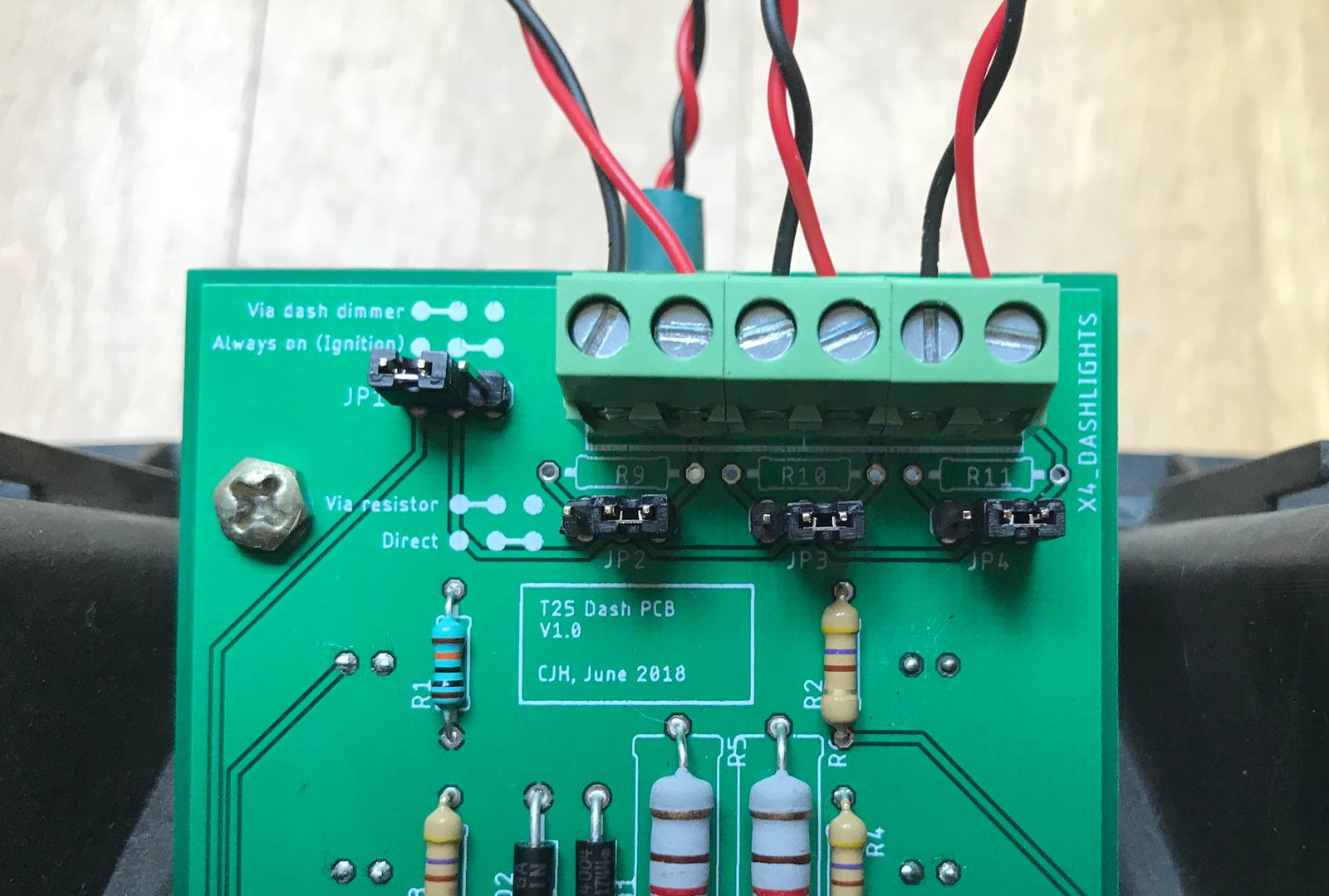
Here'a close-up of the dash illumination jumper setup.
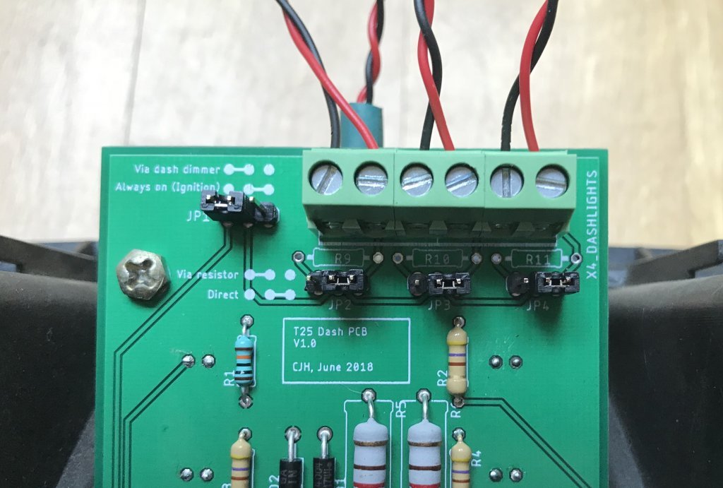
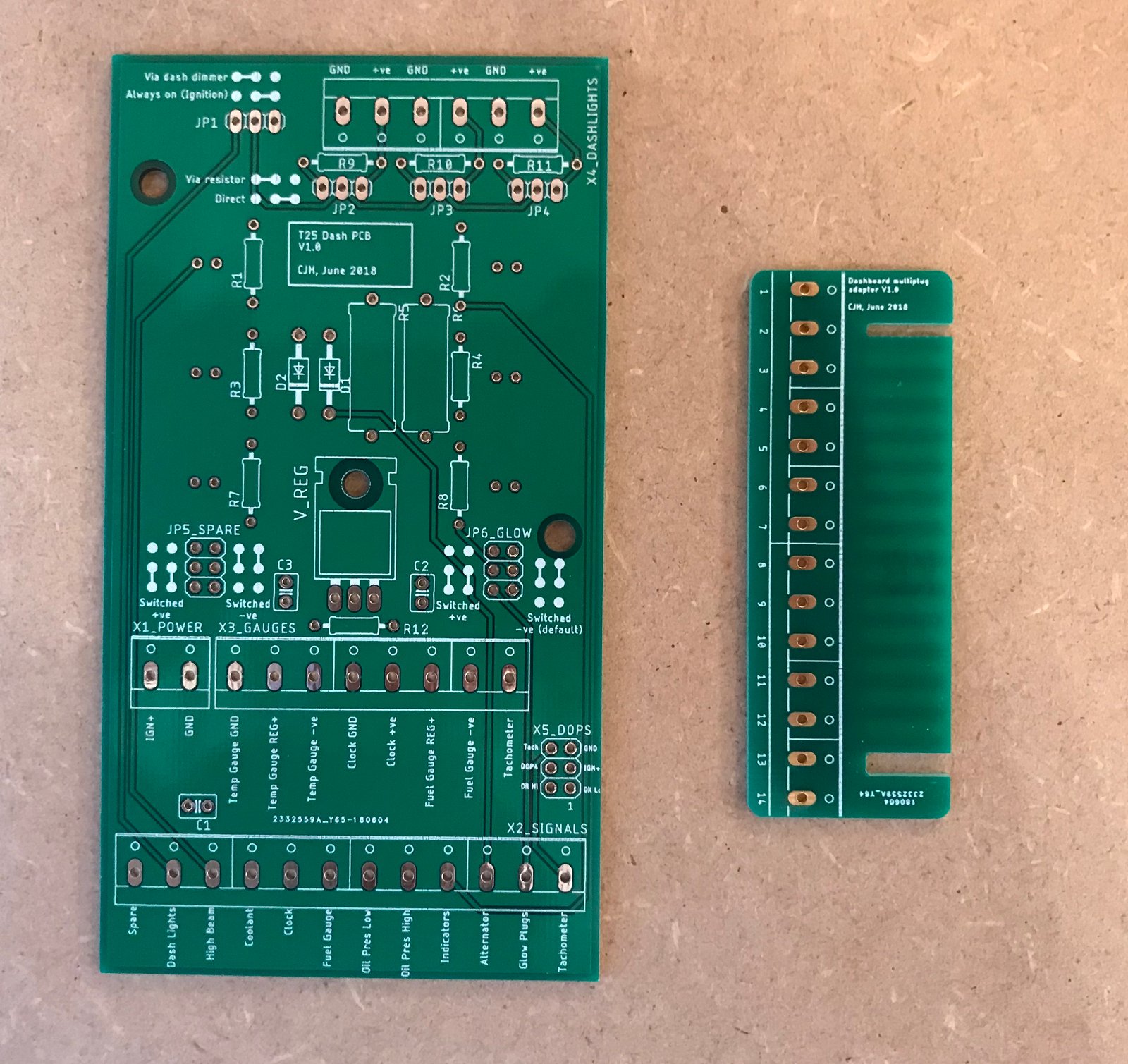
The top-left jumper is set so that the lights feed comes from the dashboard dimmer, so they'll only come on with the vehicle lights, and they can be dimmed if your bulbs allow that. The other setting takes the lights feed directly from ignition live, so that they're on whenever the ignition is on, and they can't be dimmed. The other three jumpers are set so that the bulbs are fed with all the current the feed can supply - that's because I'm using 12V LED bulbs. If you want to use low voltage/low current LEDs, the jumpers can be set to pass the source through current limiting resistors R9, R10 and R11. I haven't populated those resistor positions on this board - no point with my 12V LEDs.
.
I connected up to my van's multiplug - nothing went bang, and it all seems to work. I'll now refit the dash properly and see how it fares for a day or two. Then I'll fix the niggles and order the next iteration.
New niggles discovered today:
The LED housing fouls on the solder lugs behind the dashlights configuration pin headers - will move them a few mm up for the next version.
I found some more issues with the terminal labelling (coolant and fuel gauge terminals are incorrectly labelled as +ve) - simple fixes.