Page 11 of 17
Re: Tacho options for a petrol dash?
Posted: 04 Aug 2018, 09:51
by CJH
I just checked the back of a spare speedo. There is provision for a Hall effect sensor which was used to feed a cruise control unit on some vans. The original Hall effect sensor is NLA, but there's a
replacement available from GoWesty. But as far as I can see, a simple Hall effect sensor is very cheap, and it would be straightforward to mount one near the spinning disk part of the speedo (maybe with a little PCB if necessary), so then we'd have our pulses for measuring speed.
In previous discussions of building an Arduino rev counter the discussion has been about counting pulses - with the relatively low rate of tachometer pulses (33Hz at idle) and speedo pulses (no idea, haven't done the sums) I wonder how that approach compares to the use of something like the SAK215 to convert pulses to current.
Re: Tacho options for a petrol dash?
Posted: 04 Aug 2018, 10:04
by CJH
CJH wrote:We now have the means to convert coil pulses to current, and could presumably measure the current digitally. I didn't check, but presumably the voltage on the SAK215 also changes with current, so maybe that's easier to measure digitally.
I checked with my spare tacho board - gauge voltage varies (almost) linearly with rpm. I expect that voltage is easier to measure on an Arduino or RPi board. So the tacho circuit and a variant of it will give us 'road-speed-to-volts' and 'engine-speed-to-volts'. Half way there already!
Tacho options for a petrol dash?
Posted: 04 Aug 2018, 11:03
by bigbadbob76
So the challenge has been accepted.

If you take the output from pin 6 of the SAK you'll get volts referenced to ground.
Speedo rpm should be wheel rpm as the drive comes off the front wheel hub which makes things easy.
Good call on the hall sensor.
Arduino would be better than RPi. RPi doesn't like it's power just crashed off. It likes a proper shutdown.
I'm in pizza hut the noo so will have a think and comment later.
Sent from my iPhone using Tapatalk
Re: Tacho options for a petrol dash?
Posted: 04 Aug 2018, 11:45
by CJH
bigbadbob76 wrote:So the challenge has been accepted.
Kind of. I really must get outside more.
bigbadbob76 wrote:If you take the output from pin 6 of the SAK you'll get volts referenced to ground.
Speedo rpm should be wheel rpm as the drive comes off the front wheel hub which makes things easy.
Good call on the hall sensor.
Arduino would be better than RPi. RPi doesn't like it's power just crashed off. It likes a proper shutdown.
All good tips, thanks. Yeah, wheel rpm should be easy to convert to speed, but I'm not sure how many pulses a Hall sensor will generate per revolution - depends on the number of magnets in the spinning disc I think. I suspect it's more than one - possibly 8. I may get some and do some testing. If it's 8 pulses, then 60mph is about 105Hz (standard wheels and tyres), which is very similar to the tacho rate (ABD 4th gear, 60mph = 3233 rpm = 108Hz), so the same tacho circuit could easily be calibrated in this range.
Good point about the RPi - I use one as a music server and it runs on Tiny Core Linux, which runs entirely from memory and therefore doesn't mind having the power cable pulled suddenly, but Arduino is probably better suited.
Re: Tacho options for a petrol dash?
Posted: 04 Aug 2018, 12:24
by CJH
bigbadbob76 wrote:
If you take the output from pin 6 of the SAK you'll get volts referenced to ground.
Am I right that this is only true when there's a load where the gauge should be? Is there any reason why this voltage would be better than the voltage across the gauge outputs?
Tacho options for a petrol dash?
Posted: 04 Aug 2018, 15:37
by bigbadbob76
Yes, you need the gauge or a 50 ohm resistor as a load.
If to take the voltage from pin 5 it will be inverted. Ie: referenced to +10v.
Arduino circuit/code will be much simpler if taken from pin 6 where it's referenced to ground.

Sent from my iPhone using Tapatalk
Re: Tacho options for a petrol dash?
Posted: 05 Aug 2018, 10:10
by CJH
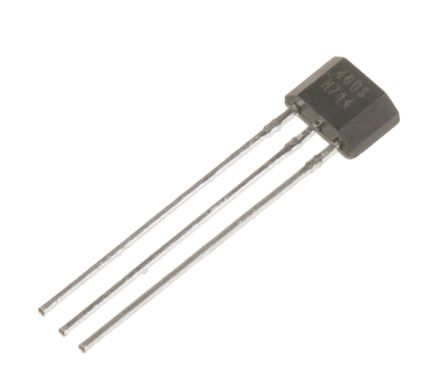
Looking for advice on Hall effect sensors.
Would something like
this be suitable? The supply voltage can be between 3 and 24VDC, so would suit a 12V or 10V feed from the dash. It has a 20mA switching current - is the speedo likely to generate that? Would the output be suitable for direct connection to pin2 of a SAK215?
Re: Tacho options for a petrol dash?
Posted: 05 Aug 2018, 12:14
by CJH
bigbadbob76 wrote:Yes, you need the gauge or a 50 ohm resistor as a load.
If to take the voltage from pin 5 it will be inverted. Ie: referenced to +10v.
Arduino circuit/code will be much simpler if taken from pin 6 where it's referenced to ground.
That makes sense. I did find something about measuring voltage with Arduino/Rpi - there's a four or eight channel analog-to-digital converter that seems to be commonly used (
MCP3004/8), and the pins can be used in pairs to measure differential voltage. Obviously it's best not to 'waste' channels that way. I think we'd be looking for speed, rpm, oil pressure, oil temperature, water temperature, fuel level, maybe outside temperature, so we're already up to 7 inputs.
Anyway, using my spare tacho board that's been bench calibrated for 4-cylinder coil pulses, I checked the voltage between pin 6 and ground (i.e. the voltage across a 200 Ohm R4), and got the following chart. I converted pulse frequency to MPH assuming standard wheels and tyres (2.047m circumference) and a speedo that generates 8 pulses per revolution. It's clearly highly linear, and corresponds to the relationship: MPH=64.03 x volts.
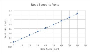
I think it would be easy to create any relationship, such as 1V=80mph, by adjusting RV1, exactly as I did for the tacho calibration. Perhaps a higher voltage at 'top' speed would be better to improve resolution. I think the aim would be to define a given relationship, then use GPS on the road to manually adjust RV1 (or enter a different constant into the software) until it displays the right speed - that would cater for any wheel/tyre combination.
Re: Tacho options for a petrol dash?
Posted: 05 Aug 2018, 14:07
by CJH
GPS raises an interesting option - why bother with a speedo input at all? With a cheap GPS add-on for an Arduino board, you'd have a reliable absolute speed (almost) everywhere. There are a few places where GPS won't give an accurate speed output (tunnels, 'urban canyons', underground car parks etc) but they're very few. Alternatively, and this might be a case of running before I can walk, how about an option to just plug in a GPS that outputs NMEA on a serial port, get the van up to a steady speed, and then press a 'calibration' button on the device to calculate a calibration scale factor between 'true' GPS speed and speedo speed - it would give you automatic compensation for different tyre sizes, tread depths etc.
Maybe I should learn how to code for Arduino first.

Re: Tacho options for a petrol dash?
Posted: 05 Aug 2018, 14:24
by Cobra88
Oh dear it's all going off on a Tangent

Re: Tacho options for a petrol dash?
Posted: 05 Aug 2018, 14:33
by CJH
Cobra88 wrote:Oh dear it's all going off on a Tangent
Very true! I think the tacho board is now done, so probably I should start a new thread for the dash computer. I was just reluctant to do so because these things have a habit of dying a death, but if Bob and/or others are up for contributing to circuit designs etc, it would be a fun project, even if it never makes it to finished product.
Re: Tacho options for a petrol dash?
Posted: 05 Aug 2018, 16:22
by CJH
I dug out an old MEGA2560 Arduino board, and discovered that it has analogue input capabilities without an external A-to-D converter. So I connected it up to measure the voltage across R4, and I couldn't understand why it appeared to fluctuate between a constant maximum and zero. Then I realised that the lower frequency inputs, leading to lower voltages, simply reduced the amount of time that the Arduino measurement appeared to be at the maximum value - the 'duty cycle' I guess. So I think the Arduino is sampling so fast that it's seeing the individual output pulses of the SAK215. I guess a standard voltmeter (and tacho galvanometer) smooth and average those pulses to show a voltage that's a function of the duty cycle. So some sort of capacitor might be needed to smooth those pulses so that the Arduino sees a smoothed voltage, or maybe I can just do some arithmetic smoothing.
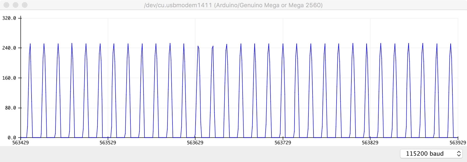
But then I thought that the Arduino might be able to see the individual pulses of the coil, so I hooked it up directly to the output of my signal generator running at 200 Hz (equivalent to 6000rpm) and sure enough, it not only sees every pulse, but it seems to sample the shape of the rise and fall of each pulse.
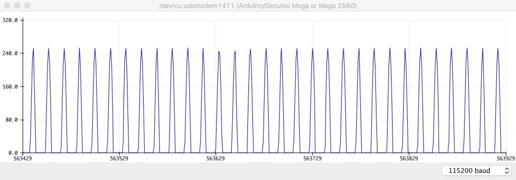
So if it can cope with a 200Hz signal, it should be able to cope with up to 6000rpm on the engine speed, and up to 120mph on an 8-pulses-per-wheel-revolution speedo. No need to go through the frequency-to-volts conversion, just count the pulses and divide by time to get frequency directly. The coil pulses will obviously have to be tamed so that they're suitable for connecting directly to the Arduino board, but I'm assuming something like the input section of the tacho board will work here (a big resistor and a zener diode). Bob? Angelo?
Re: Tacho options for a petrol dash?
Posted: 05 Aug 2018, 16:31
by CJH
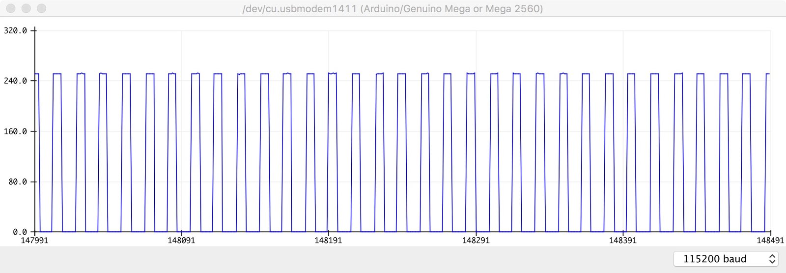
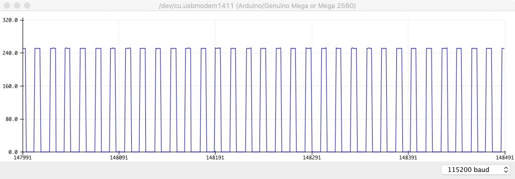
Wow - this Arduino board is surprising. Just to check whether it's actually sampling the shape of the signal I switched the signal generator from a sine wave, in the image above, to a square wave. There's detail in the square tops of the pulses, so obviously several samples per pulse.
Re: Tacho options for a petrol dash?
Posted: 05 Aug 2018, 19:02
by bigbadbob76
You're well ahead of me on this one Chris.
I'm just back from a weekend of headbanging to Iron Maiden so havn't had a chance to look into this.
Back at work tomorrow so I might get a chance to look at hall effect sensors.

20mA switching is a maximum value, you don't have to drive it that hard.
I think the maximum input on the analogue inputs to the Atmega chip are +/-5V, though that might be 0-+5v.
so 100MPH=5V sounds good.
On the other hand, not converting it to a voltage but sticking with measuring frequency and displaying it as a speed is probably the way to go.
I'm sure there are arduino libraries to do that.
The sample rate is usually half the clock speed, so it's good for Mhz frequency measurement.
Re: Tacho options for a petrol dash?
Posted: 06 Aug 2018, 08:36
by bigbadbob76
CJH wrote:Now I miss my clock.
I'm just going to go with one of these stuck in the dash where the oem one should go if it will fit behind your PCB.
 https://www.ebay.co.uk/itm/38x26x17mm-D ... 1438.l2649
" onclick="window.open(this.href);return false;