Page 10 of 11
Re: Fuel Gauge/Sender Variants
Posted: 22 Oct 2018, 13:09
by bigherb
bigbadbob76 wrote:
The VR was to allow for different sender resistances but I think we've established that the senders are all the same.
Lost the plot where we were with these. Changed a late tank and the readings where
Empty 170 ohms
Full 36 ohms
Re: Fuel Gauge/Sender Variants
Posted: 22 Oct 2018, 15:06
by bigbadbob76
Going by this-
34 Ohms = Post-85 Full
37 Ohms = Pre-85 Full
168 Ohms = Post-85 Start of Reserve
288 Ohms = Pre-85 End of Reserve
I think we decided it was the way the spec was written that was different rather than the sender.
BUT.... your measurements suggest differently Bigherb, cheers for the figures, I've lost the plot too now.

I think we need the VR Chris.

Re: Fuel Gauge/Sender Variants
Posted: 23 Oct 2018, 15:26
by bigbadbob76
Ok... my resistors are, vr1 replaced with 470ohm fixed, R1 is15k, R2 is 8k2.
My sender is a late one.
Sent from my iPhone using Tapatalk
Re: Fuel Gauge/Sender Variants
Posted: 29 Oct 2018, 00:06
by CJH
bigbadbob76 wrote:Ok... my resistors are, vr1 replaced with 470ohm fixed, R1 is15k, R2 is 8k2.
My sender is a late one.
I've ordered some PCBs this evening, so with a bit of luck they'll be here next weekend.
I've ordered 13k 0.25W for R1, and 5k for VR1, giving a range from 13k to 18k. Your VR1+R1 = 15470 Ohms, which is right in the middle of that range.
I've already received a few of the ICs, so hopefully I can build up a PCB next weekend. Presumably I can set it up approximately with a bench supply by setting a suitable voltage, corresponding to the desired gauge position, on the sender input and then adjusting VR1 until the led triggers.
Re: Fuel Gauge/Sender Variants
Posted: 05 Nov 2018, 18:32
by CJH
The PCBs arrived today - a little later than anticipated because I ordered some more multiplug adapter 'fingers' boards as well, and they add a day to the manufacturing because of the gold finish.
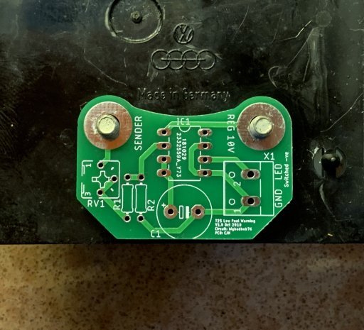
First test - they fit the fuel gauge studs perfectly. Good start.
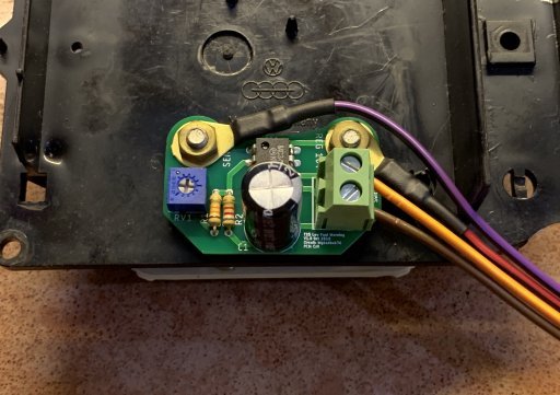
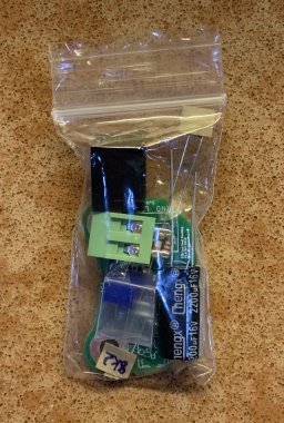
I built one up. Only takes about 10 minutes as there are so few components. The orange-and-yellow wire will go off to one of the spare LED inputs on my dash PCB, configured for 'switched -ve'.
I haven't tested it yet, so it could be a disaster if I didn't implement bigbadbob's circuit properly. To test and adjust it I was thinking I could just put an adjustable voltage on the sender stud, but the circuit also needs the regulated 10V supply, and since I've only got the one adjustable bench supply I can't provide 10V *and* that adjustable voltage. So I think I'll just play around with different resistance values between the sender terminal and ground, as I did when working out where the needle will sit.
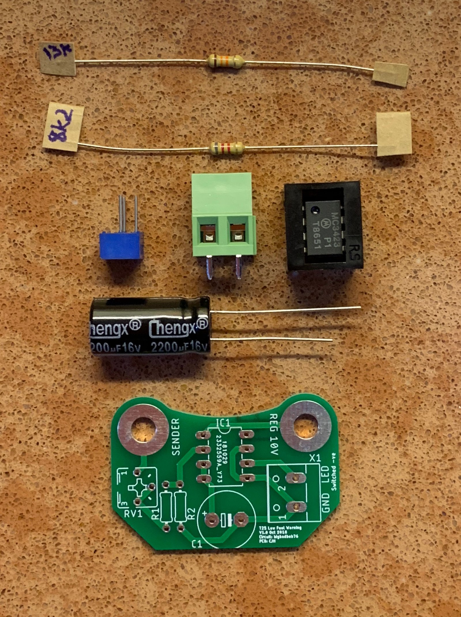
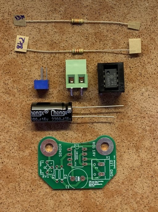
If it works, this is what a kit might look like. The 'MC3423' IC is the only part that I wasn't able to buy in quantity.
Re: Fuel Gauge/Sender Variants
Posted: 10 Nov 2018, 14:02
by CJH
Had a bit of time today to get a run at a few jobs, so I've fitted and adjusted my fuel light board.
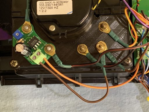
The orange-and-yellow wire goes off to the LED6 input on my dash PCB. The bit that took the time was adjusting the variable resistor so that the LED triggers at an appropriate fuel level. The long time-constant in the circuit, which ensures that the light doesn't flash with every bend or hill, means that it takes a while to check each tiny adjustment of the resistor. It was made worse in my case because one of the 5k variable resistors that I purchased turned out to be 20k, so even tiny movements of the adjuster screw make quite a big difference. I checked the others and they're all 5k, so I was just unlucky to get the wrong one.
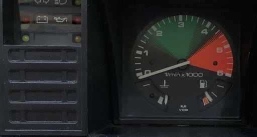
Anyway, I've ended up with what I think is a suitable adjustment. With the sum of R1 and RV1 adjusted to be ~16900 Ohms my light is off when the fuel gauge is at 160 Ohms, at which point the needle is a little above the red:
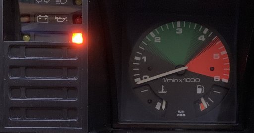
The LED comes on at 180 Ohms, when the needle is just entering the top of the red;
Time for a bit of road testing.
Re: Fuel Gauge/Sender Variants
Posted: 12 Nov 2018, 13:10
by CJH
The low fuel light works rather well on the road. My tank was getting towards empty, but the light wasn't coming on with normal cornering or the occasional incline. It takes about 30s of continuous 'low' signal to trigger the light. I got the fuel level down to the point where long but very slight uphill inclines would trigger it, and very slight downhill inclines would put it out (it's surprisingly difficult to find local roads that are perfectly flat). At that point I filled up, and got 55 litres in, meaning I had about 1 gallon, or ~20-23 miles (not sure whether the tank drains completely when empty though), left. That's just about perfect I think. It will start to flash occasionally before that point, if I go up long hills for instance, so that should be all the warning I need.
I do plan to finish my basic Arduino version, for comparison. I'll work on the accelerometer version when I have more time, but in the meantime it should be easy enough to implement a 30s averaging filter to mimic the hardware version, and I'll try to get it to trigger the other spare LED, so that I can compare them in use.
Re: Fuel Gauge/Sender Variants
Posted: 13 Nov 2018, 08:43
by bigbadbob76
Looks very neat Chris.

I used a spare gauge and a combination of fixed resistors in place of the sender to set mine.
Re: Fuel Gauge/Sender Variants
Posted: 15 Nov 2018, 20:09
by bigherb
Fitted one of CJH's low fuel warning lamp kits.
Quick to make up only 15 minutes.
Mines an early dash still with the pc ribbon.
Stuck some gaffer tape over the PC ribbon to stop any rubbing on the PCB tags, used the original fuel gauge nuts as standoffs for the PCB to help with rubbing.

No spare LED tags on the PCB to fit additional LEDs so used a remote LED warning lamp below the instruments.

Earthed the PCB on the voltage regulator earth and power for the led from the gauge V+

Set the PCB pot the midpoint and used a variable resistor to work the gauge which switched the LED on around 15Ltr.
I have a near full tank at the moment so I will do the final adjustments when the fuel is near the reserve but it is looking good. Thanks to Chris and Bigbadbob.
Re: Fuel Gauge/Sender Variants
Posted: 15 Nov 2018, 20:33
by bigbadbob76
That looks a neat install BH.
Can you solder to the existing tracks on the flexi PCB to fit an extra LED? there should be a resistor slot on the flexi for it too.
Cheers Chris, I got my kit today, 2 mins to solder the components and 10 mins to find where I'd left my snips to trim the component legs.
Re: Fuel Gauge/Sender Variants
Posted: 15 Nov 2018, 21:17
by bigherb
bigbadbob76 wrote:That looks a neat install BH.
Can you solder to the existing tracks on the flexi PCB to fit an extra LED? there should be a resistor slot on the flexi for it too.
I could have done but I didn't want to push my luck with a working original ribbon and it was quicker to fit a remote LED near to the ones I already have for the trailer flasher and sidelights.
And thanks for doing the circuit.
Re: Fuel Gauge/Sender Variants
Posted: 16 Nov 2018, 09:09
by CJH
bigherb wrote:bigbadbob76 wrote:
Can you solder to the existing tracks on the flexi PCB to fit an extra LED?
I could have done but I didn't want to push my luck with a working original ribbon...
Got to agree with Bigherb here - I soldered some wires onto the dash light tracks on my old PCB, and the plastic around the attachment point does melt very quickly. Of course it doesn't matter if it melts locally, but it's quite a risk to take with a good original PCB I'd say.
I've totted up the cost of the parts for the low fuel board. Now that I've found a cheaper source for the IC, the biggest single cost item is 'shipping and duty'. The cost of that is not an exact figure, since I have to work out a split for the shipping and duty between other parts that I ordered in the same parcel. But I reckon £4.50 should cover it if it's included with a dash PCB kit, or £5.50 if posted separately.
I've got parts for 7 kits. I'll wait to see if there's any interest before ordering any more.
Re: Fuel Gauge/Sender Variants
Posted: 17 Nov 2018, 03:17
by Claudio ZAMPIERI
Bonjour
Je intéresse par votre travail, c'est fantastique...! Comme vous l'avez compris je suis Francais précisément de La Rochelle et je vous recherche depuis longtemps. Beaucoup de passionnés de VW T3 n'arrive pas à greffer un compte-tours, ou un nouveau Cluster 180€ sur site campervan
nous avons pas les compétences électronique comme vous.
Pouvez vous nous aider à faire un cluster qui remplace la feuille bleu...? Dans mon cas, j'ai un compteurs de MK1 avec 2 jauges et une montre analogique à greffer...je peux vous faire des photos précise
je suis particulier et avec autres passionnés, qui cherche une solution
merci a bientôt
Claudio ZAMPIERI
zampieri.claudio@neuf.fr
Re: Fuel Gauge/Sender Variants
Posted: 17 Nov 2018, 06:25
by kevtherev
Claudio ZAMPIERI wrote:Bonjour
Je intéresse par votre travail, c'est fantastique...! Comme vous l'avez compris je suis Francais précisément de La Rochelle et je vous recherche depuis longtemps. Beaucoup de passionnés de VW T3 n'arrive pas à greffer un compte-tours, ou un nouveau Cluster 180€ sur site campervan
nous avons pas les compétences électronique comme vous.
Pouvez vous nous aider à faire un cluster qui remplace la feuille bleu...? Dans mon cas, j'ai un compteurs de MK1 avec 2 jauges et une montre analogique à greffer...je peux vous faire des photos précise
je suis particulier et avec autres passionnés, qui cherche une solution
merci a bientôt
Claudio ZAMPIERI
zampieri.claudio@neuf.fr
Hello
I'm interested in your work, it's fantastic ...! As you understand, I am French precisely from La Rochelle and I have been looking for you for a long time. Many VW T3 enthusiasts fail to graft a tachometer, or a new 180 € Cluster on site campervan
we do not have the electronic skills like you.
Can you help us make a cluster that replaces the blue sheet ...? In my case, I have a meter of MK1 with 2 gauges and an analog watch to graft ... I can make you precise pictures
I am particular and with other passionates, who seeks a solution
Thanks see you soon
Re: Fuel Gauge/Sender Variants
Posted: 17 Nov 2018, 06:46
by kevtherev
Once again awesome work fellas.
Not just discussion, actual practice.
As much as I would like having a low tank fuel light, as an LPG user, it would be on, constantly.
But, the OMVL fuel switch has an led indicator.
I have no idea what it bases the level on, But it does fluctuate with cornering, so I'll assume it's the actual liquid level in the pressurised tank.
Would this be an indication of another resistance based guage?