Page 9 of 17
Re: Tacho options for a petrol dash?
Posted: 31 Jul 2018, 18:51
by CJH
bigbadbob76 wrote:
AngeloEvs wrote: The application sheet for that SAK 215 is about the worst I have ever seen........

yeah, it's woefully short on detail.

That's encouraging - I thought it was just my lack of knowledge, but if you two have found it unhelpful too then I don't feel so bad.
Re: Tacho options for a petrol dash?
Posted: 01 Aug 2018, 08:30
by bigbadbob76
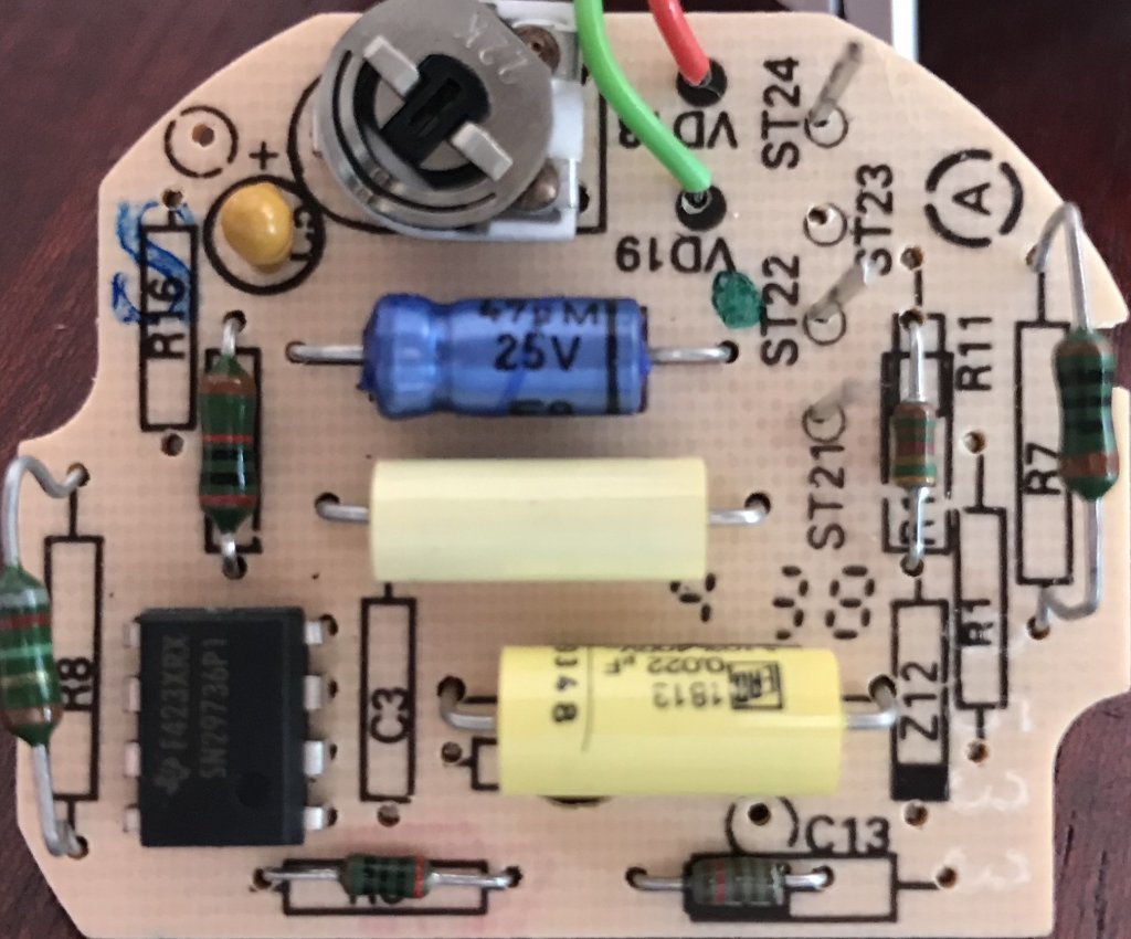
CJH wrote:If that pink 'resistor' is in fact a capacitor, what is it's value?
looking back at your diesel board-
and assuming the board is used for both diesel and petrol but with different components....
C3 is not used in the diesel but is in the same position as the "pink resistor" so it looks like it's not a resistor at all but IS a capacitor.
On mine, that capacitor is 22nF.
The pink one is probably 10nF.
Re: Tacho options for a petrol dash?
Posted: 01 Aug 2018, 08:39
by CJH
bigbadbob76 wrote:
C3 is not used in the diesel but is in the same position as the "pink resistor" so it looks like it's not a resistor at all but IS a capacitor.
On mine, that capacitor is 22nF.
Good spot. Looking at the reverse of that board, C3 is indeed across pins 1 and 4 of the IC. But are you sure yours is 22nF? In your original sketch of the Golf board, the only 22nF cap is between pin 2 and gnd (pin 1). Between Pin 4 and GND you have a 150nF cap.
Re: Tacho options for a petrol dash?
Posted: 01 Aug 2018, 08:59
by bigbadbob76
That's true, I based the 22nF on the early petrol diagram.
My original scribble is 150nF and is what I have fitted.
Just occurred to me, my tacho FSD is 7K rpm and has a 162 ohm meter resistor.
Your tacho FSD is 6K rpm, and has a higher (191) resistor.

That's where the precision resistor comes in.
If you use 2K, your FSD won't be 6K rpm even if you tweak RV1 to read correctly at 2-3k rpm.
https://www.ebay.co.uk/itm/10-X-Through ... xy5jxSa79u" onclick="window.open(this.href);return false;
Re: Tacho options for a petrol dash?
Posted: 01 Aug 2018, 12:15
by CJH
That makes sense.
I've got some 191 Ohm resistors arriving today. I've also been thinking about a better way to calibrate the gauge, since I'm not certain about the offset/amplitude relationship. There are some very cheap signal generators which should satisfy the requirement. I have a £20 model on order (
https://www.amazon.co.uk/gp/product/B0748H1ZPM/" onclick="window.open(this.href);return false;).
But I'm also wondering whether an audio source could work. 6000rpm is 100Hz, each cylinder fires every second turn of the crank, making 50Hz, but there are four of them, making 200Hz. So if I generate a 200Hz audio tone and pass it through a small audio amplifier to get the volts up, maybe I already have the means to bench calibrate the gauge. I have no idea how the impedance of the tacho board compares to a pair of speakers, so I'm not sure this will work. But if it does, I could test at 6000rpm (200Hz) and 3000rpm (100Hz) and a few other points, to separate offset from amplitude. With some laptop-based audio tone generation software I can even play with different waveforms to get something like a coil spike waveform if necessary, but that probably isn't necessary since the SAK215 evidently works with a sine wave, since it works with the alternator W terminal for the Diesel versions.
Re: Tacho options for a petrol dash?
Posted: 01 Aug 2018, 14:05
by bigbadbob76
if you fit the 191 resistor you only have to tweak RV1 so it reads the same as your digital tacho clipped on a plug lead.
Yes, 6K rpm = 200Hz. so you could do it that way if you can get enough volts out of your pulse generator.
I'll have a look at my old valve "Wayne kerr" (yes really

) sig gen and see how high it goes
You could inject it directly into pin 2 and then you only need a couple of volts amplitude.
input impedance of pin 2 is 7k ohms according to the datasheet.
Re: Tacho options for a petrol dash?
Posted: 01 Aug 2018, 14:14
by CJH
bigbadbob76 wrote:if you fit the 191 resistor you only have to tweak RV1 so it reads the same as your digital tacho clipped on a plug lead.
Sure, but doing that accurately at several engine speeds isn't easy, and getting the engine up to 6000rpm while leaning over it is a bit scary!
bigbadbob76 wrote:
You could inject it directly into pin 2 and then you only need a couple of volts amplitude.
That's a possibility - might even be able to get that from a decent 'line level' audio output.
Re: Tacho options for a petrol dash?
Posted: 01 Aug 2018, 14:21
by bigbadbob76
I'm pretty sure I still have a 5v square wave generator that will do 200hz too. might give it a go.
with the 191 in place you just have one adjustment so you can just set it at say 3K and not need to go to 6K.
Re: Tacho options for a petrol dash?
Posted: 01 Aug 2018, 14:38
by CJH
Yeah, but it’d be more accurate if set at 6000rpm, and a lot more precise (and comfortable) if done on the bench. The cheap signal generator I’ve ordered does +/- 10v apparently.
Re: Tacho options for a petrol dash?
Posted: 01 Aug 2018, 14:45
by Cobra88
Yep on the bench for sure
Think the DG is in the red at 5,400 rpm

Re: Tacho options for a petrol dash?
Posted: 01 Aug 2018, 15:12
by AngeloEvs
Bench and sig genny only way I would do it. Also, for a 1.9 DG I would probably be focusing on calibrating for usable RPM range i.e. 1000 to 5000 ........6000? Not my old bus.......
Decent little sig genny that for £20, 10v output should be ok and I would select square wave for testing and calibration but a signal generator with 5v output will probably be too low, but if it does struggle just add a simple transistor switching circuit with a 12v supply to the sig genny output.
Re: Tacho options for a petrol dash?
Posted: 02 Aug 2018, 08:04
by bigbadbob76
AngeloEvs wrote:a signal generator with 5v output will probably be too low.
yeah, definitely too low for connecting to the tacho input but I was suggesting connecting directly to pin 2 of the SAK215 which triggers as low as 1.5V.

Working back from that, you'd need at least (1.5+5.6)x((33+3.3)/3.3)= 78V to trigger the tacho input using Chris's late circuit.
The LT side of the coil will reach this value by back EMF as the circuit is opened by the ignition module.
It's not just 12V as you might think.
My early circuit doesn't have the zener or the resistor to ground so relies on the 7k input impedance of the SAK215 as part of the potential divider
and would need at least 1.5 x ((33+33+7)/7)=15.6V
And just for completeness, a diesel would trigger as low as 1.5x((15+7)/7)=4.7V
Re: Tacho options for a petrol dash?
Posted: 02 Aug 2018, 08:33
by CJH
Thanks for that Bob - saves me wasting my time trying to use the signal generator on the normal signal input. I'll go straight for pin 2.
Re: Tacho options for a petrol dash?
Posted: 02 Aug 2018, 12:57
by bigbadbob76
Here's another interesting diagram-
Supposedly using a Mic2/C chip which I can't find any data on but the pinout and component values are the same (ish) as our SAK215 circuits.
Note that they suggest changing the value of the resistor between pin4 and supply to adjust for swapping to a V6 or V8 engine and the same would presumably apply to diesels with different pulley sizes.
Different No of pulses per rev depending on number of cylinders suggesting that our RV1 is frequency dependent.
Whereas their resistor between pin6 and ground is the same 191 ohm.
Although his tacho fsd is 7krpm which is slightly confusing but will be meter current fsd dependent.
Re: Tacho options for a petrol dash?
Posted: 02 Aug 2018, 21:05
by CJH
bigbadbob76 wrote:
Note that they suggest changing the value of the resistor between pin4 and supply to adjust for swapping to a V6 or V8 engine and the same would presumably apply to diesels with different pulley sizes.
Different No of pulses per rev depending on number of cylinders suggesting that our RV1 is frequency dependent.
Whereas their resistor between pin6 and ground is the same 191 ohm.
Although his tacho fsd is 7krpm which is slightly confusing but will be meter current fsd dependent.
Interesting find. Yes, RV1 controls the amount that the needle swings over for a given pulse rate - it's the only adjustment available for calibrating and for 'converting' the Diesel version from one pulley size to another. So by definition it is the frequency dependent part: e.g. make the needle move half as far for a given pulse rate to convert from 4 cylinder to 8 cylinder (I think that's the right way).
I could do with some guidance on the use of the signal generator that arrived today. Two questions:
1) Power is via a small DC jack (5V, centre +ve), and it comes with a USB cable for this purpose. The output is via a BNC socket - signal on the centre pin presumably, and earth on the outer body. If I want to use this to test the tacho board, where should the signal earth go? Assuming I power the signal generator with a USB adapter, and the tacho board with a 12V supply from my bench supply, is it ok to tie the signal earth to the tacho board earth, even though the signal generator supply earth might be at a different potential? Should I run my USB adapter from the bench supply's 12V as well, just so that everything has the same earth reference?
2) My Draper multimeter has a frequency setting, and I can measure the output of the signal generator. I found I had to nudge the signal generator up to 203Hz before the multimeter said it was getting 200Hz (199.7 actually). Which one should I trust more?