Page 8 of 11
Re: Dashboard PCB Replacement (CJH Design)
Posted: 16 Aug 2025, 16:13
by TwinTurbo
Is assembly doing the LED's , do they have the height from the board?
Rob
Re: Dashboard PCB Replacement (CJH Design)
Posted: 16 Aug 2025, 16:25
by The Hairy Camper
TwinTurbo wrote: ↑16 Aug 2025, 16:13
Is assembly doing the LED's , do they have the height from the board?
Rob
Yes, I had to leave a remark with JLCPCB regarding this. They are being installed with spacers. It's all included in the BOM and CPL files too, so it shouldn't be an issue.
Re: Dashboard PCB Replacement (CJH Design)
Posted: 21 Aug 2025, 14:56
by keynsham1
Is there an issue with GPS speedo's or is it just a personal opinion? I just wondered as I sometimes use my phone as a digital GPS speedo and it has always worked and seems to be deadly accurate when compared to those flashing signs that tell you your speed as you approach them.
Re: Dashboard PCB Replacement (CJH Design)
Posted: 22 Aug 2025, 00:49
by TwinTurbo
have a read of the Class M IVA manual section for Speed indication I suspect that it would fail an IVA if done on rollers in a building, which would be the same in a tunnel/ But at an MOT it would not be picked up.
I am dabbling with a GPS receiver module , i am getting message data but being indoors during initial testing proved to be fruitless as expected.
Re: Dashboard PCB Replacement (CJH Design)
Posted: 01 Sep 2025, 13:15
by Dstan0710
I would be interested once avilible for sure
Re: Dashboard PCB Replacement (CJH Design)
Posted: 10 Sep 2025, 10:48
by The Hairy Camper
Well something finally arrived this morning.


JLCPCB seemed to struggle with the spacer instructions? There were only 2 different spacers in the instructions! Not sure where the 3rd has come from?


Fits perfectly though


So, there are a few things to tackle. The heatsink doesn't fit in it's allotted space on the PCB. I added a copper/lead free hasl fill to the design though, so the prototypes should work just fine without them. I also added a connector to make the voltage regulators removable/replaceable. I'm not sure if these will work well without the heatsink though?
I will have to sort out some replacement LED's as the spacers have caused some confusion (even though JLCPCB recommended them). Oh, and they ran out of green LED's, so the indicators are blue at the moment

I'm made up that I finally have them though. I'll hopefully have some time to test them over the next day or 2.
Cheers
Re: Dashboard PCB Replacement (CJH Design)
Posted: 10 Sep 2025, 11:34
by Stesaw
As someone whos first PCB disintergrated along with the rev counter backing (which I now have sorted i hope) and now has an old dodgy blue PCB held together with tape hope and dreams with no working temp gauge driving as a daily, I'm watching this closely.. CJH's inital ones were priced very reasonably I dont want to be paying ballpark £200 if I can help it for a repair cluster from companies when someone cooked up one at the fraction of the price.
If you're going to be making a few runs of them, please let me know.
Re: Dashboard PCB Replacement (CJH Design)
Posted: 10 Sep 2025, 11:36
by TwinTurbo
As per other thread, I may now have a dimensionally accurate rev counter backing.
I am still very busy and any vehicular tinkering is very limited to "must do" at present. Maisie goes for MOT retest on Friday which is priority getting her sorted.
Rob
Re: Dashboard PCB Replacement (CJH Design)
Posted: 10 Sep 2025, 18:50
by The Hairy Camper
I made a bit more progress this evening. I soldered in a green LED for the for the indicator and replaced the High Beam LED so it's the correct height. I left LED 6 where it was as I'm not sure I'll use it anytime soon?
I removed resistor R3 as this could interfere with the DOPS system on my Dash. I also installed the voltage regulator with a heatsink for the time being.
I wanted to do some wiring, but I am knackered now.
It's good to see it coming together. Hopefully I'll do some more tomorrow.


Re: Dashboard PCB Replacement (CJH Design)
Posted: 11 Sep 2025, 18:18
by The Hairy Camper
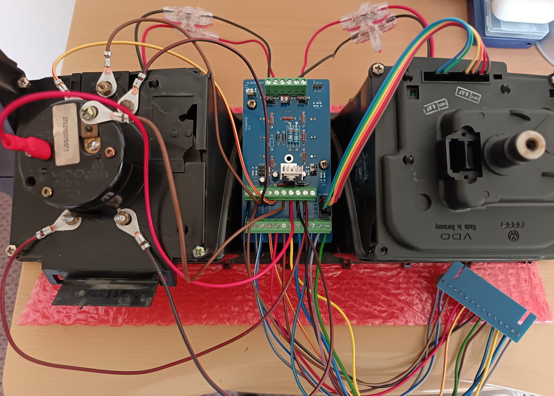
Right, I got some wiring done this evening. I had most of the right colours, but brickwerks were short 3 of them so I had to improvise. I had to order some jumper caps too, as the PCB's didn't come with them. They should be here tomorrow though and hopefully I'll be able to test this over the weekend.


I could use some help from anyone familiar with box headers and IDC ribbon cable connections though.
Below are some pictures of the box header connector for the DOPS system. JLCPCB soldered it on the wrong way (I do need to send them an email), but for the time being I planned on using female dupont connections for the DOPS system anyway.
My question is, do I have these connections on the right pins? I'm pretty sure I have connection 1 in the right spot and then 2 is the behind it. Same for connection 3 and 4, then 5 and 6.


Here is a picture of how CJH mounted his.

Cheers
Re: Dashboard PCB Replacement (CJH Design)
Posted: 11 Sep 2025, 21:55
by TwinTurbo
would have to see the other end. mine should be oriented the same.
Re: Dashboard PCB Replacement (CJH Design)
Posted: 12 Sep 2025, 17:51
by The Hairy Camper
Ok, I think it's finished. I've double checked the DOPS connections using the old ribbon PCB and I'm confident I have them in the correct order.
Jumper caps arrived today and I think I have all the necessary one's installed. I've left the LED 6 jumpers vacant.
There are a few things that need addressing before I'm happy about installing this PCB long term, but I think I've done enough to test it out tomorrow.
Re: Dashboard PCB Replacement (CJH Design)
Posted: 12 Sep 2025, 19:17
by Stesaw
The Hairy Camper wrote: ↑12 Sep 2025, 17:51
Ok, I think it's finished. I've double checked the DOPS connections using the old ribbon PCB and I'm confident I have them in the correct order.
Jumper caps arrived today and I think I have all the necessary one's installed. I've left the LED 6 jumpers vacant.
There are a few things that need addressing before I'm happy about installing this PCB long term, but I think I've done enough to test it out tomorrow.

Your picture is busted, just use the imgur upload

. If you're thinking of getting sets made what sorta price you thinking?
Re: Dashboard PCB Replacement (CJH Design)
Posted: 12 Sep 2025, 21:05
by The Hairy Camper
Is that last picture not working? I uploaded it the same way as I usually do.
Honestly, I haven't given a lot of thought to selling these kits (my better half has though when she found out how much I spent
). I'm still learning about PCB's and I still want to develop the design more. If I had a bit more patience, I would have kept on working on it. I think it's about time I test these boards though, make sure everything works before I try to change anything else.
That being said, I ordered 10 of these prototype PCB sets and can't see me needing them all.
Re: Dashboard PCB Replacement (CJH Design)
Posted: 12 Sep 2025, 21:44
by TwinTurbo
just leaver the box header off the board and turn it 180

