Page 8 of 17
Re: Tacho options for a petrol dash?
Posted: 30 Jul 2018, 18:36
by CJH
Thanks Angelo, that's helpful. If I do another iteration of the board I'll take account of the zener position. Do we want that input to be clamped to 5v6 though - isn't it the coil pulse? Do you mean that it will never exceed 5v6? The SAK215 can apparently tolerate up to 20V on the input pin.*
But I don't think I'll be doing another iteration, because after a few tests this evening I think I'm there.
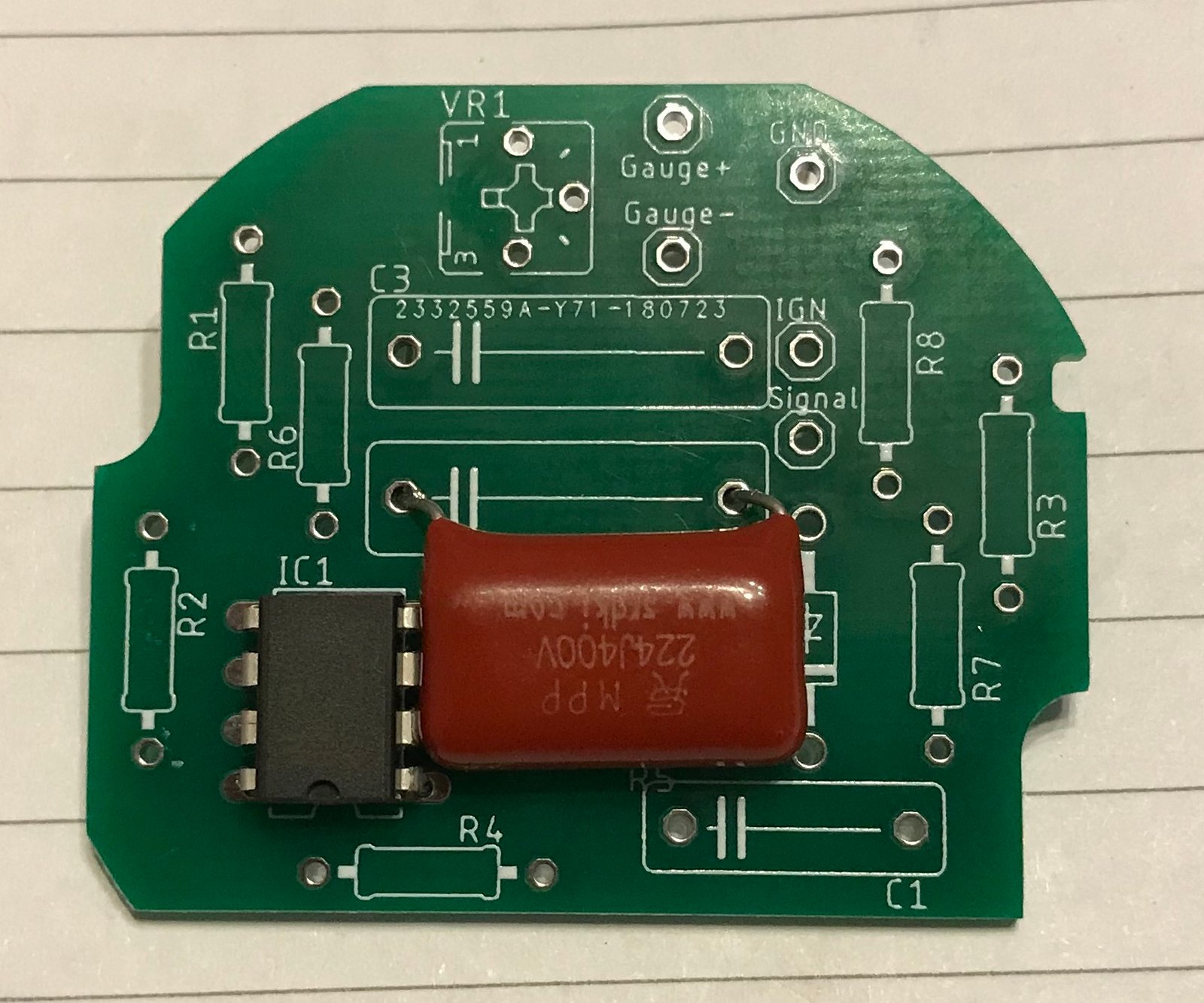
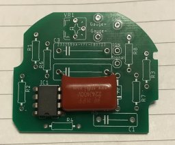
I started off with R4 set to 191 Ohms using a 1K variable, and R8 set to 802, using another 1K variable. As soon as I connected the power, without the engine running, the needle swung right over to the right. So I changed R8 to 10K, and that solved that problem. Then I started the engine, and I was able to get it spot on by adjusting RV1. Then I removed R8 altogether, and nothing changed. So evidently I can do without R8. Maybe it should be a capacitor after all - I may try that.
So then I adjusted R4 and I found that almost anything I did to that resistor could be compensated by RV1. So evidently 191 isn't a critical value. I put my original 200 Ohm fixed resistor back in there and then tweaked RV1 until it was spot-on again.
I reckon that might be it. I can use my existing PCB without modification, simply by leaving out R8, which a) should be between pins 1 and 4, not pins 2 and 4, b) may be 10k rather than 802, and c) might actually be a capacitor. Apart from that there's nothing wrong with it!

*E D I T - message crossed with Bob's
Re: Tacho options for a petrol dash?
Posted: 30 Jul 2018, 18:40
by CJH
The needle seems more stable than the multimeter, but it's difficult tell when trying to hold the rpm steady on the throttle. I'll put the tacho in the dash and run with it for a day or two to see how it performs.
Re: Tacho options for a petrol dash?
Posted: 30 Jul 2018, 18:49
by 937carrera
Not sure what motor you are doing this on, but can you temporarily adjust the throttle stop to allow a higher idle. I did the same last week when taking some oil temps / pressures.
Re: Tacho options for a petrol dash?
Posted: 30 Jul 2018, 18:56
by CJH
It's a carbed 2.1 DJ. Yeah, I could do that, but even with a fixed throttle there's still some slight variation in the rpm when it's not under load. On the road it's easier to hold a perfectly constant engine speed, and all I want to do is see how steady the needle is, to decide whether any smoothing is necessary - either replacing R8 with a capacitor or putting a capacitor across the gauge supply.
Re: Tacho options for a petrol dash?
Posted: 30 Jul 2018, 19:11
by CJH
While I've got the attention of the experts - what about the three capacitors? I had no idea what types to go for, so I went according to the capacitance values only.
What I bought:
C1: 3.3nF, 300V, Ceramic Disc
C2: 220nF, 400V, CBB (polypropylene?)
C3: 47uF, 25V, Electrolytic
C2 is a bit snug on the back of the board and gets squashed against the tacho back plate. In the photos I've seen, the two big capacitors are both axial, and therefore lower profile than my C2. What should I be using?
Re: Tacho options for a petrol dash?
Posted: 30 Jul 2018, 19:23
by bigbadbob76
What you have sounds good to me. I go electrolytic over tantalum every time. Disc ceramics can be noisy but you won't notice it in this circuit.
Poly is fond for the other one.
Sounds like you've sussed it.
Sent from my iPhone using Tapatalk
Re: Tacho options for a petrol dash?
Posted: 30 Jul 2018, 19:29
by CJH
That's a bit of luck - thank you. I've just realised that C1 is between the coil signal and GND, and mine is only rated at 25V. Is that sufficient do you think, given that the coil pulse may exceed that voltage?
Re: Tacho options for a petrol dash?
Posted: 30 Jul 2018, 20:00
by CJH
I just spotted something in the values of the resistors that I've ended up with.
When I had 191 Ohms for R4, I had to adjust RV1 to get the needle position correct. The sum of RV1+R6 came to 8.4k+20k = 28.4k
When I replaced R4 with a fixed 200 Ohm resistor, I had to adjust RV1, and the value I ended up with was 6.9k, making RV1+R6 = 26.9k
So a 4.7% increase in R4 was compensated by a 5.3% decrease in RV1+R6. That's 5% on each given the level of precision in these settings. If that's a real relationship, it's doubly surprising that they'd specify 191 Ohms, and not a more common standard value.
Re: Tacho options for a petrol dash?
Posted: 31 Jul 2018, 07:55
by bigbadbob76
C1 is after the potential divider R7/R3 so the voltage on C1 is approx. 1/11th of the signal voltage. I don't think you'll have a problem.
Re: the 5% relationship between RV1 adjustment and R4 adjustment, assuming RV1 adjusts offset and R4 adjusts gain then you still have to adjust both to the right value so the meter reads correctly at both ends of the scale, you can't compensate for one with the other at all points on the scale equally.
Re: R8, if it is a resistor, it's quite big compared to R6, why so big if it's taking the same current as R6?
Re: the zener, I see what Angelo is saying but we know the circuit works as designed by VDO so I'd leave it be, you may have to change other component values if you change the zener's orientation.
Re: Tacho options for a petrol dash?
Posted: 31 Jul 2018, 08:05
by CJH
Thanks Bob, good to know that C1 is ok.
I don't think RV1 is for offset. Two reasons: In my tests, it seems to do exactly the same job as varying R4, and in the Diesel versions, RV1 is the only means of adjusting for different pulley sizes
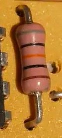
If that pink 'resistor' is in fact a capacitor, what is it's value?
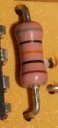
I *think* it should be read from the bottom, as I think I can see foil around the bottom leg. So that would make it:
Brown: 1
Black: 0
Orange: x1000pF
Black: 20%
Grey: 8 x100V
i.e. 10nF, 20%, 800V. Not a million miles from the 3.3nF that Angelo suggested. If my on-the-road testing shows that the needle could do with smoothing I might try one of my 3.3nF ceramic disc versions in there, assuming that's the role of that capacitor.
If I wanted to use a lower profile component for C2, what would you suggest? The current CBB polypropylene component is 1-2mm too tall for the rear mounting frame.
Re: Tacho options for a petrol dash?
Posted: 31 Jul 2018, 10:05
by AngeloEvs
There is a wide range of miniature caps available. Just search on EBAY for 220nF Capacitor to get an idea of what is available.
I would use a 100v working D.C. voltage but even so, you should see several 220nF polyester 400v that are suitable, including miniature box, axial and the most common which you could fold over if really struggling for vertical space. If I were at home I would send you some.........
BTW, the application sheet for that SAK 215 is about the worst I have ever seen........

Re: Tacho options for a petrol dash?
Posted: 31 Jul 2018, 11:05
by CJH
Thanks Angelo - I'll take a look. In fact I think I might be able to make do with the ones I've already got - I can just about squeeze the capacitor in if I lie it flat and kink the legs.
I've spent the morning finishing the install into my dashboard - fired it up and it seems to work. I'm off out in the van for the rest of the day - will report back later.
Re: Tacho options for a petrol dash?
Posted: 31 Jul 2018, 12:04
by Cobra88
Awesome
I dont have to put the diesel clocks back on fleabay

Re: Tacho options for a petrol dash?
Posted: 31 Jul 2018, 12:07
by bigbadbob76
CJH wrote:If that pink 'resistor' is in fact a capacitor, what is it's value?
10nF, 20%, 800V?
10nF, 20% seems likely, 800V seems high in that application but maybe VDO had a big stock of them.

AngeloEvs wrote: The application sheet for that SAK 215 is about the worst I have ever seen........
yeah, it's woefully short on detail.

Re: Tacho options for a petrol dash?
Posted: 31 Jul 2018, 18:48
by CJH
I've been out in the van this afternoon, and the rev counter seems perfect. No unpleasant bounce/wobble, just a nice smooth, responsive needle, so no need to bother with any additional smoothing in my opinion. And the revs seem to match the speedo pretty well - I've previously adjusted my speedo so I'm fairly confident that the error in it is small. At an indicated 60mph I was seeing ~3400, and for by ABD gearbox with standard wheels and tyres it should read 3233, so maybe my speedo is reading 3mph too low or my rev counter is reading 167rpm too high, or it's a bit of both, but whatever, the error is small.
I do have some 191 Ohm resistors on the way, and will replace the 200 Ohm R4, just in case there's something critical about that value, so I'll then do a final calibration against my multimeter. I want to experiment with some extra long header pins to make the external connection compatible with the 4mm-pitch plug on the original foil circuit board - the pads on the PCB are in the right place so this should be straightforward. My test PCB is looking a little worse-for-wear, having had a few components swapped out a few times, so then I'll build a final neat version on a fresh PCB, with that big capacitor laid flat, and then I'll button it all up.