Page 28 of 30
Re: Replacing the dashboard plastic PCB
Posted: 27 Jun 2020, 21:42
by MidLifeCrisis
I had a look at these but couldn't find one that had drilled holes that you could solder a wire into/onto - they all seem to be just pads? Or have you seen anything more useful?
Re: Replacing the dashboard plastic PCB
Posted: 28 Jun 2020, 09:38
by marlinowner
I was just going to solder to the pads but I guess you could use an edge connector permanently fixed to the board.
Re: Replacing the dashboard plastic PCB
Posted: 28 Jun 2020, 10:01
by Rotormac
It would also be relatively simple to drill 1mm holes at the ends of each land for mechanical security before soldering.
Re: Replacing the dashboard plastic PCB
Posted: 28 Jun 2020, 21:59
by AngeloEvs
Since I have PCB making equipment (and plenty of time) I would be happy to help members out if they want an edge connector similar to the one below but with an additional second row of anchor holes for soldering cables or I could change the design to accept screw terminal blocks.
Cost of materials, a beer and postage around a fiver.......
 edge2
edge2 by
Angelo Evans, on Flickr
Re: Replacing the dashboard plastic PCB
Posted: 21 Nov 2020, 18:29
by dafabv
Hi, can someone tell me the exact measurements of CJB's board please.
Re: Replacing the dashboard plastic PCB
Posted: 25 Nov 2020, 19:53
by Geato
@dafabv I just signed up to this forum because of this thread.
I have recreated this board and edge connector in Altium but I need to confirm the mounting hole locations before signing off. I reverse engineered the PCB from the photos shown by CJH earlier in the thread. I was planning on putting it up on Github for all to access. I am using surface mount parts however I chose ones that are physically large so they are easier to solder. Once it is finished, I can export it to ASCII file format so many other PCB design tools can import it. I was considering replacing the wiring bundle with an IDC ribbon cable for a much cleaner installation but I have decided to make a flex circuit (foil) replacement for the 86+ right now. I prefer this route as one can still use the original bulbs or their LED equivalents and less connections to break. Once completed, I will make a pre '86 flex.
Re: Replacing the dashboard plastic PCB
Posted: 13 Dec 2020, 13:48
by Claudio ZAMPIERI
I ordered a PCB replacement kit from Chris (CJH),
this kit is really great, he's a genius!
But as you know Chris is not coming back

I would like to know if anybody here can reproduce the same PCB kit as Chris to make?
Re: Replacing the dashboard plastic PCB
Posted: 06 Aug 2021, 11:44
by Italjohn
My PCB from Chris


Re: Replacing the dashboard plastic PCB
Posted: 07 Aug 2021, 09:01
by Robsey
If it is just the edge connector, then AngeloEVS can produce these.
He made me one for my digital dash adapter lead.
Very reasonably priced but excellent quality.
I don't want to say cheap as that could infer bad quality. These are great.

As for the rest of the looms and connectors.
I suspect that it is well within his abilities.
Just gathering and assembling the necessary parts.
Re: Replacing the dashboard plastic PCB
Posted: 07 Aug 2021, 09:13
by Robsey
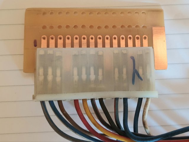
Looking at your later photo, I can only see three connectors.
The blue quad-lock style dash connector,
The three pin speedometer drive plug
And the edge connector.
Overall quite a simple adapter loom.
It is just a matter of seeing which wires from the blue connector go where.
Only the edge connector would need to be made to order. The other two plugs should be available to buy from various online shops.
Re: Replacing the dashboard plastic PCB
Posted: 21 Aug 2021, 11:46
by ianders
I had forgotten about this thread. I had some PCBs printed back in 2019 by using some of the circuits and images from earlier in this thread. Was having a dig around the shed and came across a couple of these.
If anyone wants one, give me a shout. Have one unpopulated board and one mostly populated along with 8 of the edge-connector finger boards (1 of these is populated). I've installed one of these in my van and is working fine, but this is my first attempt at PCB design so no warranty etc.
If someone wants to test it out and it's all good, I can look at uploading the files (Eagle / Gerber) or getting more printed and putting together some "kits".


Re: Replacing the dashboard plastic PCB
Posted: 13 Oct 2021, 17:54
by ScienceBoy
Is it the engine speed, ie revs at position 9?
Re: Replacing the dashboard plastic PCB
Posted: 14 Oct 2021, 07:11
by Robsey
Assuming "the most typical" configuration.
Must admit that I wasn't aware of ItalJohn's wiring variation before his post.
According to my notes, yes
Pin 9 is for the engine rpm signal - green wire.
Best guess is to follow the wire colours to the 14 pin dash connector plug.
Overall, the wiring colours did not change that much between model years.
My 1983 dash loom used the same colours (in a different order) as my planned 1987 loom.
Replacing the dashboard plastic PCB
Posted: 19 Dec 2021, 08:38
by DoubleOSeven
https://www.slaughterhousecustoms.com/p ... ement-unit

I have no affiliation with this company & haven’t tried this pcb replacement either but worth noting, I thought.
Re: Replacing the dashboard plastic PCB
Posted: 19 Dec 2021, 20:59
by ajsimmo
Also available via Brickwerks. Just fitted one and works a treat. Just a slight issue with early v late diesel pcb configuration for glow plug light, but very quickly sorted and great customer service.
Sent from my moto g(30) using Tapatalk
