Difference between revisions of "VW Electrics Upgrading headlights"
Ghost123uk (talk | contribs) |
Hacksawbob (talk | contribs) |
||
| Line 95: | Line 95: | ||
[http://www.syncro.org/Wiring.htm] | [http://www.syncro.org/Wiring.htm] | ||
Auto electric supplies for relays and wiring http://www.autoelectricsupplies.co.uk/ | |||
http://members.ozemail.com.au/~pjlander/Headlights.htm post fusebox 4 relay version highest available watts this way. | http://members.ozemail.com.au/~pjlander/Headlights.htm post fusebox 4 relay version highest available watts this way. | ||
Revision as of 10:27, 11 November 2014
link titlelink title==Alternative headlamps==
Blingpanzer: & California Dreamin
If you're already on H4 headlamps and the reflectors are clean and corrosion-free, upgrade to OSRAM Nightbreaker Plus+ or Philips Xtreme bulbs(the Osrams can be picked up for around £15.00 a pair). They are the same wattage as the originals but newer production techniques and technologies mean they produce a much brighter whiter light. However, even with these new improved bulbs, T25 headlamps suffer from VW's decision not to fit relays to the majority of the range. See below how old wiring and switch contacts do not allow the bulbs to get full power and as a consequence there is a lot to be gained by retrofitting relays.
[[File:Media:Example.jpg]]==Relays and voltage drop==
CumbrianKeith:
The graph below was constructed by Keith Morris (aka CumbrianKeith) and represents Hella's published light intensity output against supply voltage for a typical headlamp bulb. It indicates why a small drop of applied voltage (due to direct switching contacts, bad earths, too thin wire for instance) can result in very poor headlight brightness. Read on to be amazed how poor your light can be! He used a relay and heavy duty wiring to transform his headlights - there are tailor-made relay and wiring kits available from the States (ask on vanagon or syncro forums) but these parts can be acquired in the UK too of course.

From the 80-90 Tech 2004 message boards, 31-03-2004
Fitted H4 optics and even with 100/80 w bulbs the lighting level is not great. So I've been reading this article
http://dsl.torque.net/images/Relays.pdf
and did the voltage drop measurements as described to ascertain how the old wiring, terminals and switches have affected the juice flow. I get a total voltage drop in the main beam circuit of 3.4 volts! This equates to allowing through only 75% of the supposed 13.5ish which should be happening. So I plot a graph of the Hella research figures and extrapolate a figure of around 30% light output compared to what it would be if voltage was 100% of the alternator output (which is actually only producing 12.9 with the lights on)
Maybe this is why the lights are poor... So I get some nice thick (27amp) cable and some relays and wire it all up (and get some 130/90s just for the hell of it - cos I can!) and lo and behold the voltage drop now is only 0.05v and boy are those lights bright!
Qu: Only slight problem and this is where my question comes in: The mainbeam tell-tale on the instrument panel now doesn't work - it flashes momentarily when you put the lights up but doesn't stay on; and it doesn't come on at all when you flash the heads without the other lights on.
Ans: - Pick the relay signal feed up off the left-hand headlamp, not the right. The latter doesn't trigger the tell-tale!
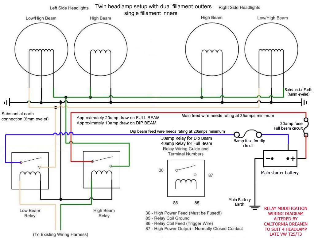
California Dreamin Open the links below to see a wiring diagram I modified for a 4 lamp setup (later 4 rectangular type) The diagram uses the existing wiring to 'switch' two relays (dip & full beam circuits). All wiring is fused and I've built in redundancy so dip and full beam run on seperate circuits so if one fails the other will still function. The diagram uses new wiring on the feed and earth sides of the lamps for minimum voltage drop. I realise that relays can be installed internally but these use the old tired wiring to the lamps so cannot gaurantee the best feed to the lamps.
[http://i239.photobucket.com/albums/ff270/andre1paparazi/HeadlightRelayWiringDiagramcopycopycopy.jpg http://s239.photobucket.com/user/andre1paparazi/media/HeadlightRelayWiringDiagramcopycopycopy.jpg.html [URL=http://s239.photobucket.com/user/andre1paparazi/media/HeadlightRelayWiringDiagramcopycopycopy.jpg.html][IMG]http://i239.photobucket.com/albums/ff270/andre1paparazi/HeadlightRelayWiringDiagramcopycopycopy.jpg[/IMG][/URL]]
Relay Position options

HarryMann:
Also, using 'bulb grease', Holts NoCrode or similar on bulb contacts helps keep the voltages up where it matters - see CumbrianKeith's output Vs Voltage graph above
Headlamp relays and dim-dip
VWlewis:
If you are installing headlight relays on a 1987 through to 1991 T25's built for the UK market it might have Dim Dip circuit fitted.
\Normal dipped is supposed to be bright. dim dipped is different, it only works with side lights setting ( 1st position on the light switch) and only when the engine is on! the dim dipped option supplies a reduced voltage via a large resistor to the main dipped headlight circuit when the engine is on and the sidelights are on.
The Dim Dip resistor must be (can be) disconnected (see below for dispute)*. It can be found behind the RH side headlamp assembly. It is easy to find as the resistor is a big fat wire wound resistor that looks like an old fashioned electric fire element, wrapped in tape, screwed to the bodywork behind the off side headlamp. It's about 8 or 10 cm long, and about 1.5 cm thick. The wires connecting the resistor to the headlight assembly can be disconnected at a connector close to the resistor. Make sure you insulate any bare wires and connectors to ensure no fire starts due to earthing of these.
Description of the Dim-Dip Lamps (UK Only) - Here
joshb: * I am very curious to know if and why I need to disconnect my dim dip circuit when fitting headlight relays. I can see no reason why I would need to, but wonder why It says in the Wiki that you MUST disconect it. cheers
Synro G: Dimdip equals dipped beam at slightly reduced voltage (reduce the voltage a bit power goes down a lot, it's a more extreme version of what your fitting relays for - think dimdip is about 8-9V).
The dimdip circuit joins the dipped beam circuit in the fusebox just before the loom splits into left and right fuses and wiring. This is the circuit you use to trigger the new dipped beam relay, but depending on where you take your relay trigger depends on how it behaves with dimdip.
If you fit relays after the fusebox (most seem to do it this way), besides losing the use of the headlamp fuses, dimdip feeds into the relays with enough current to trigger them, thus conecting the headlamps to the full power surply meaning what was once dimdip becomes full power dipped beam - you won't be able to have dim (sidelightish) level lighting when the engine is on. Disabling dimdip means you just get sidelamps on the first position like when the engine is off, non British spec. or more modern vehicles are like this anyway so it doesn't matter.
If, like me, you fit the relays between the dipswitch and the fusebox everything still works as OEM, you still get the headlamp fuses on the fuseboard, full headlamps are still brighter as you've by-passed all the switches and their slight voltage drops, and dimdip still works as it comes in after the relays.
joshb: So, if your lights are bright on sidelight then it it means the dim dip (if fitted) is triggering your relays for full brightness. I fitted my relays so the dim dip still works as normal when the sidelights and engine are on, so I guess I am OK.
Ballast unit
CovKid
Agree on the Osrams but I also fitted a headlight booster (a sort of ballast unit) that I found on the web for around £35. That was the biggest improvement by far. Fairly large (about the size of a catering box of matches) - managed to tuck mine under the dash.

Please don't ask me where to buy them. They came up on ebay (emanate from China or similar). No, there's no makers name
Links, references
Syncro.org [1]
Auto electric supplies for relays and wiring http://www.autoelectricsupplies.co.uk/
http://members.ozemail.com.au/~pjlander/Headlights.htm post fusebox 4 relay version highest available watts this way.
Added by Ghost123uk = From Chris, 80-90 member "CJH" = "This photo shows the difference between the new wiring to the OS light [with a relay] and the old original wiring to the NS light - if anything it's more marked in real life."
