VW Electrics Dash Fan Control Upgrade
(Article penned by Covkid 04/08/2016)
Why fit a PWM controller to the dash fan and what is PWM?
This project came about through early discussions with Ghost123UK. We concluded (on the maths alone) that controlling the fan using pulse width modulation (PWM) would be far more efficient than using the resistors that VW fitted, and potentially form part of a basic climate control. We couldn't see why PWM wouldn't work on the blower motor and as you'll see below - it does. I have since posted a two-part summary on Youtube.
A PWM controller also works out cheaper to buy than replacing the resistors and is much less taxing on cables and battery), arguably less of a fire risk, and you get infinite control right up to the flat out speed of the motor rather than thew click-notch control fitted as standard. Car manufacturers tended to use resistors (and some still do today) as they're cheaper to produce, but they tend to be power-hungry and can get very hot. This probably matters less in a car, but in a camper its important to conserve power as much as you can, even if its the starter battery.
I'll skip the science, but basically, PWM involves the power being switched on and off to the blower faster than you could do it yourself, almost like a variable strobe, rather than all the excess current used up in heat via the resistors. If you ever played with small DC motors as a kid, you'll know that even when the power is disconnected briefly, the motor will still spin on a little, and that whats at work here - plus there is the luxury of being able to set any speed you want from zero to flat out speed.
Some time ago I put up a video summary to show how it works using a brand new blower motor. See:
https://www.youtube.com/watch?v=3GzJ8N1Rqp8
https://www.youtube.com/watch?v=3S24Hty4_bs
I don't really recommend this mod with a worn out blower, but rather with a new one, or one in good working order. Old electric motos can draw considerably more power just to start them up which is why some owners experience a blown fuse or uprate the fuse to compensate - not a good move. If yours is close to 30 years old, it is due for replacement, at which point you may wish to try this upgrade at the same time. It has little impact on cosmetics. If your blower uinit is in good condition, you can fit a PWM controller with the dash in place fairly easily.
Where can I buy a suitable controller?
I bought my DC PWM controller from ebay for well under ten pounds. You'll need to search. You want a 20amp one (for headroom) and it needs the control knob on a flylead so you can mount it through the facia. Its actually a simple circuit but you do have to find the relevant wires to connect it all up..
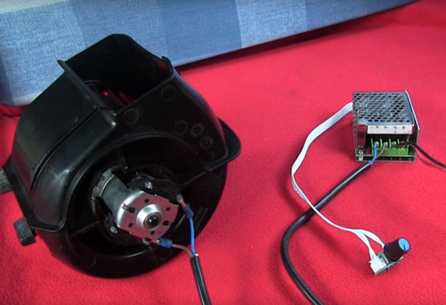
Heres the basic setup (uninstalled). The blower fan (left) is hooked up to the controller box (right) and the speed is controlled by the small potentiometer (bottom right).
To install one (see photo below), and completely bypass the resistors, you'll need to get to the relevant cables.
Identifying blower cables
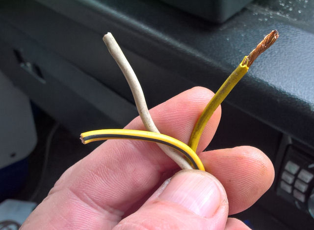
There are a couple of things you need to bear in mind when connecting the PWM controller. Firstly, on a 3-speed blower, there are three wires that come out of the blower unit (see photo) plus an earth. If you cut these wires at the blower switch and remove switch completely, you can then pull them up via the ashtray and follow the cable bundle further down to the blower box and locate the brown earth wire - you'll need this. I managed fine peering down there with a torch.
You'll need to disconnect the battery, remove the ashtray and the blower facia by pulling off the lever knobs and carefully prising off the facia. This will expose the speed control which can be unclipped and the three wires behind, cut off. Theres also a red/black wire which is the power to the fan.
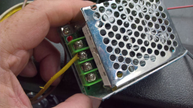
The blower wires you actually need to make controller work are the yellow one (which is top speed) and the brown earth. Both of these MUST go direct to the output of the controller. If you don't connect them both directly to the controller output, it will NOT work. The controller needs them both - all to itself. The yellow cable is actually the one wire that doesn't depend on the resisors, which is what we want. The other two, yellow/black (speed 2) and grey (speed 1) are not needed as the controller will be handling lower speeds from now on. You can snip those two and tape them up.
Adequate patch cables
The other point to bear in mind is that any patch cables you use MUST be at least as thick as the yellow wire as it carries some current and if you use thinner wire it WILL heat up and could cause a fire so make sure all cables including negative wires are up to the job. Get this right from the start. Yellow to positive output, brown to negative output.
Applying power
Once those two cables are connected to controller, you need to get power to it. I recommend you find a point at fusebox that is ONLY live with ignition on. You're hardly likely to need the blower when parked (even though VW appears to have wired it like that) and besides without the engine running it would soon flatten your battery so choose an ignition live connection. If you really need cool air when parked, a USB-powered fan is a better idea anyway. That way with ignition off, the fan and controller get no power whatsoever and are therefore isolated. Connect this ignition live cable to the + terminal on controller input.
You can soon find an ignition live at the fusebox, by seeing which fuseway is live when you turn the ignition key to first position, although you may find a closer connection if you're lucky.
Unlike the output, The earth on the input can come direct from the chassis - or wherever is convenient. The controller can sit on top of or to the side of the stereo unit. You can mount it in there if you like or just ensure it can't move around but does at least have some space around it for airflow. The controller knob cable can then be fed under the dash blower levers and pulled through the hole where the old switch used to be.
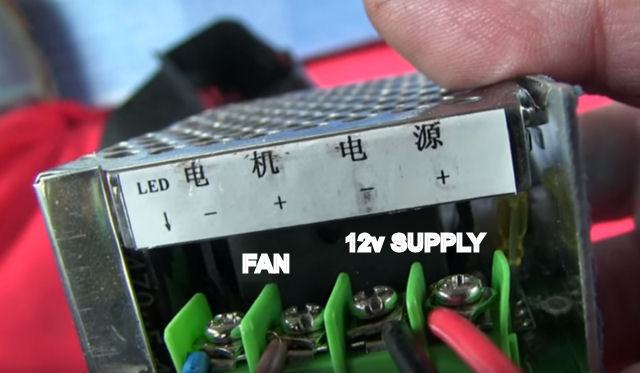
Photo below should help you decipher the Chinese symbols if you're unsure. On the left, yellow and brown (to fan), and on the right your 12v (ignition live) source. Ignore the colours I've used here for the fan as it was while I tested the unit.
At this point, with battery reconnected and ignition on, the controller knob should work. Time for a celebratory cuppa that only the Brits understand!
Mounting control knob
Tea drunk, plus a few biscuits, now for the trickier bit. To fit control knob, you could just make a hole elsewhere in the dash but I wanted to at least mount it in the same place.
There are two ways you could do it but usually the shaft on the control knob is rather short, and certainly too short to go though the complete thickness of the facia which is in four parts. You could (in theory) desolder the potentiometer and find an exact match with a longer shaft but this could prove extremely difficult. The other way is to alter the back of the blower control facia to accept it. I opted for this method.
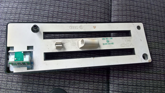
The facia is four distinct layers. They can be taken apart and adapted to suit without affecting the outward appearance at all.
From the back they are:
1. Bulb holder layer
2. Clear plastic light spreader
3. Printed layer
4. Black plastic facia
See photo below.
Getting the four layers apart (they are partially glued) will take patience and a flat blade. Don't bend them too much or you may risk cracking them. Take your time and work in good light on a table - not in the cab!
The reason you need to separate them is the back and central perspex layer will require minor cutting to accept the control knob assembly as one, and that will leave just enough room to attach the washer and nut on the front. If you try to cut through without doing this, you risk damaging the printed layer or facia. This was about the neatest arrangement I could come up with on the bench although you may come up with an alternative method.
The clear plastic layer was originally intended to be used as a backlit affair - essentially a piece of perspex lit by a bulb. Where the bulb meets the clear plastic, you'll see its been split and chamfered to direct the light along the plastic - in much the same way you can light the edge of a perspex sheet with LEDs these days - albeit with a tungsten bulb.
I have to say, unless you use an incredibly bright bulb (and at risk of melting the plastic), its not a particularly effective backlight at all, although perhaps in pitch black it is good enough and LEDs generally run at much lower temperatures.
Back to fitting control knob!
See following photos for reference. I haven't been specific by including measurements as your control knob assembly may be different from mine but the principles remain the same.
A dremel-type tool makes much easier work of it but I managed fine by scoring the plastic with a sharp knife and nibbling it away with pliers. You'll need to cut through the back layer as well as the clear plastic layer, just enough so the control knob assembly fits in there and butts up square against the printed and facia layers.
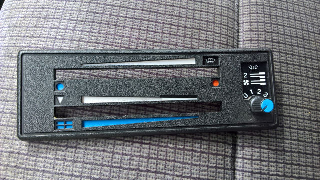
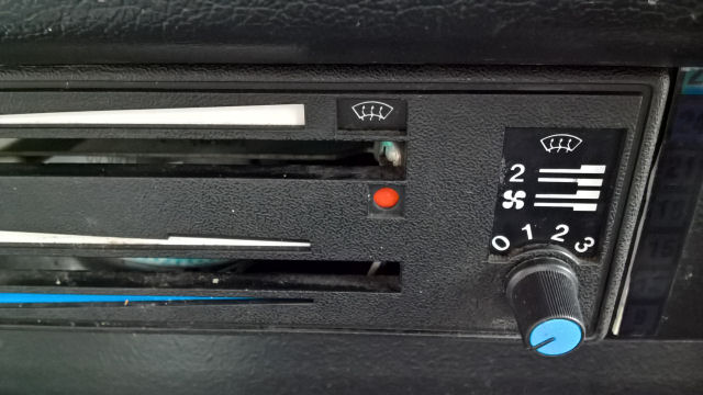
This is the front (below). I actually like the knob that came with it as it matches the blue on the facia perfectly but you could fit what you like.
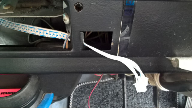
Feeding the control knob plugs through the original controller hole in the dash.
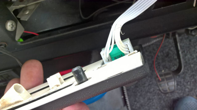
Plugs connected, the whole panel is ready to refit. Use a little glue to ensure the back layer isn't loose.
Facia panel refitted.
I couldn't find a reliable way to reuse the original knob since its an entirely different fitting and araldite did not appeal to me in the slightest. However, for the complete purist, I'm sure its possible to do this.
Ensure that the printed circuit on the control knob assembly does not foul the metal dash. Insulate it well and if required, cut a slightly larger hole where the original switch went to give a little more clearance. Ensure controller is protected by a fuse. 15amp should do it. If you're using an existing blower that will only work with something like a 25amp fuse, its time it was replaced I'm afraid. You will probably kill the PWM controller otherwise.
