Petrol engines aircooled - Crankshaft oil seal
By: Anthony & Lee Carey
Introduction
Due to unwanted oil stains on the front drive it was decided to change the crankshaft and gearbox oil seals. Encouraged by comments on this site how relatively easy the engine and gearbox were to remove, we pressed ahead.
Here is a brief record of the experience illustrated with pictures which I hope maybe of use to others who are tempted to have a go. Before attempting please ensure that the engine battery is isolated and that the van is secured. Safety must be paramount and all things are attempted at your own risk. ………………………………………………………………………………………………………………………………………………………………………………………………………………………
Cost of components
Approx. £70 total(not including hire of hoist)
Crank shaft oil seal from VWHeritage.com (Genuine VW component), also felt washer and flywheel ‘O’ ring
Gear box seal, Blue Hylomar adhesive from GSF
Engine oil from Halfords
Gearbox oil Screwfix
Clutch alignment tool (Draper) £13 approx
Clutch slave cylinder from EBay £25 approx
Detaching major components
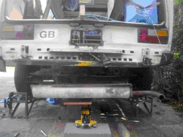
Ideally chock front, jack-up and prop, rear wheels off for best access, then drop driveshafts by removing inner CVJ's from transaxle drive-flanges. Wear disposable gloves, MOS2 grease! Can refit wheels if using ramps rather than large props to give ground clearance for engine drop (jack stands should be big, strong & stable!).
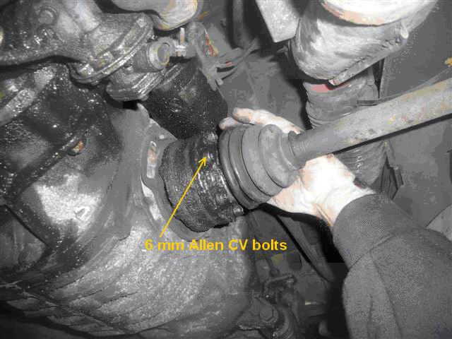
CV joints secured with 6mm hex socket cap-heads (Allen bolts). Ideal tool is a long hex bit in 3/8 sq. socket drive with various extensions, (available from Halfords). Sometimes 12 point spline bolts are used.
Clean out the sockets first with a v.small screwdriver so bit goes fully in, tap it right in and ensure you're on it dead straight before attempting to untighten (rotate shaft to best position for each bolt, then helper applies brakes - makes it faster) - round one off and you'll need plenty of experience to get it out and waste a lot of time! Renew bolts if any way damaged; don't forget the small crinkle washers. NB. A good time to check inner & outer CVJs, replace or re-grease - Ed
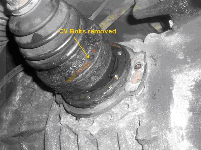
CV joint disconnected, should be covered with a plastic bag and tied up out of the way.
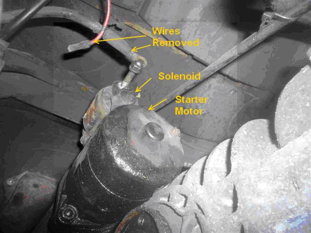
Starter motor and solenoid wires removed, this also allows the lead to the alternator to be unplugged and removed.
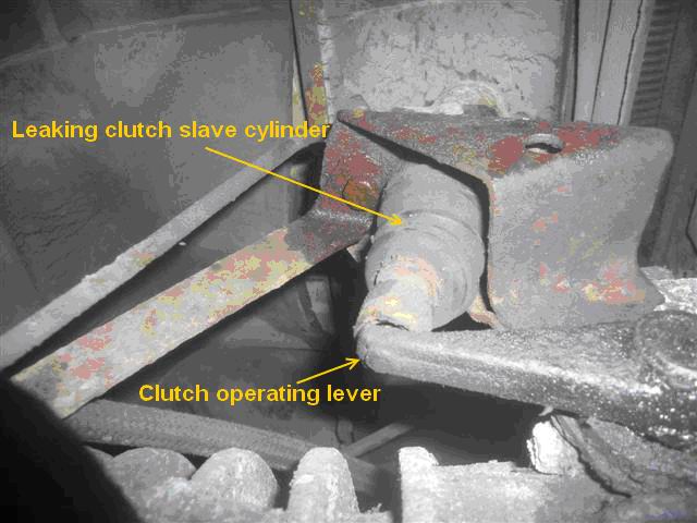
Clutch slave cylinder mounting. My cylinder was leaking, with the rubber boot full of fluid. I decided to replace the cylinder, obtained on EBay for £25 approx. Or VW Commercial parts or GSF/JK etc.
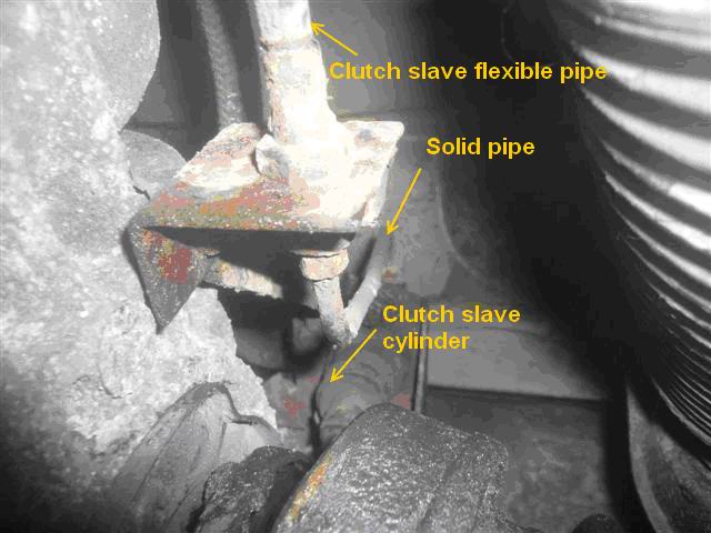
Clutch slave cylinder pipe arrangement, remove pipe clamp from side of gearbox.
Do not remove clutch hyd line unless changing slave, see also Slave replacement and Slave cyl and pipework problems Also, Pipe spanners useful - Ed
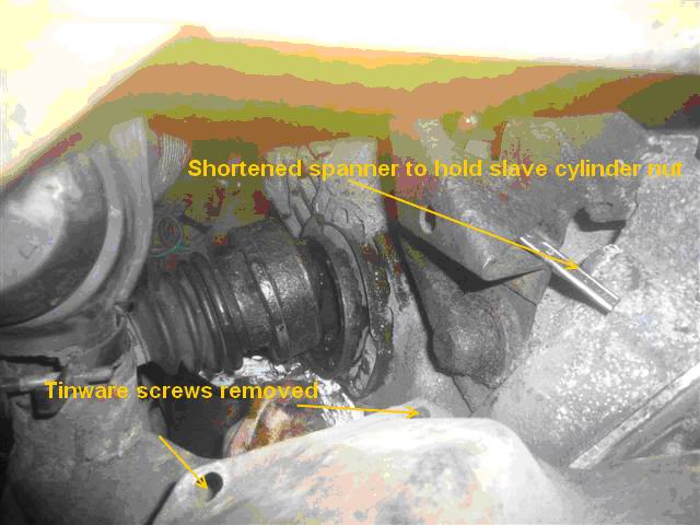
Clutch slave cylinder removed. Note shortened 13mm spanner still in place used to hold cylinder mounting bolt. The two tinware screws are removed to allow hand access from top of the engine bay (the tinware at the rear of the engine bay can be bent forward allowing a hand to be inserted to hold the spanner).
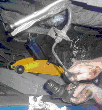
Recovering clutch slave cylinder, note pipe clamped with Mole grips to prevent fluid loss (be careful, proper hydr hose clamping tool best - Ed).
Engine removal
Before the engine can be lowered:
Drain the engine oil
Remove carburettor, throttle cable and spring
Disconnect wires from reversing switch on side of gearbox
Unbolt guide pin for gearbox linkage and tie up shaft
Remove engine oil filler and dipstick
Remove ignition leads and distributor cap
Disconnect brake vacuum hose
Disconnect wire to oil pressure switch and alternator
Unclamp heater flapper boxes to heat exchangers
Once the engine is supported remove the four nuts on engine bearer and four bolts on gearbox mount
Lower engine to floor using two trolley jacks or a hoist.
Engine lowered on trolley jack using wooden batten and rope across engine bay in case jack slips
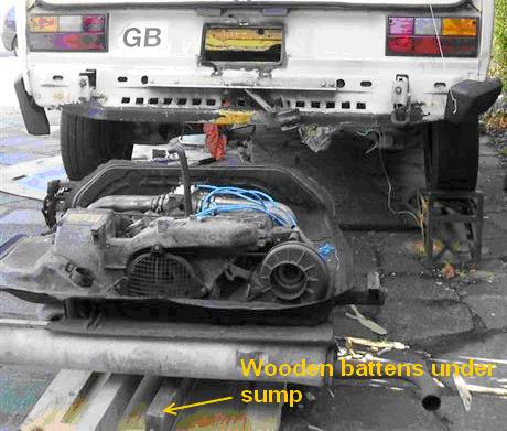
Engine lowered on to old door, wooden battens under sump to avoid engine weight on heat exchangers and dragged from beneath the van.
Oil seal fitting
Gearbox removed showing oil contamination. It is a good idea while the gearbox is out to drain and replace gearbox oil.
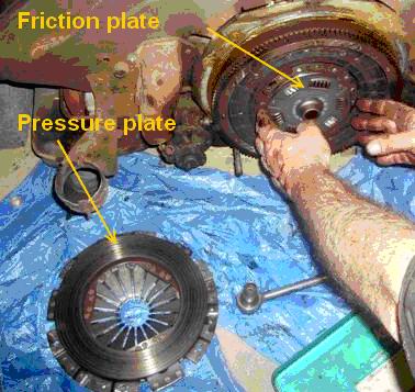
Removing clutch components (Luckily the friction plate has not been contaminated by the oil leak).
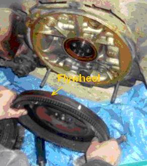
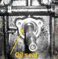
Flywheel removed revealing leaking oil seal. The flywheel needs to be locked in order to remove bolts (see below).
Crankshaft end-float on these engines is important, so if high-mileage, check this is within spec. first (see shimming later) -Ed.
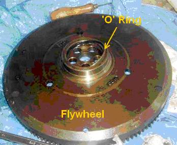
Flywheel after removal, note the ‘O’ ring secured in a slot. In order to undo the flywheel securing bolts the flywheel has to be locked to prevent it turning. I found that the easiest way to do this was to screw in one of the clutch pressure plate securing bolts and by using a double ended ring spanner lock it to one on the bolts securing the bell housing to the engine. The same method can be used when replacing the flywheel. Both ‘O’ ring and felt washer should be replaced.
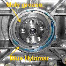
Oil seal removed and Moly grease applied to shims. Blue Hylomar solution applied to seat in readiness for the fitting of the new oil seal. Prior to this the flywheel should be jury fitted and the crankshaft end-float checked (see Haynes for limits). Replace/add shim(s) if necessary to give correct play.
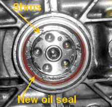
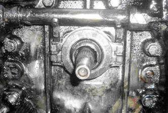
New crankshaft oil seal fitted, ready for flywheel and clutch. Hylomar not abs. necessary. Drive in dead straight, either tapping altrnate sides or use a large well matching plate or tube. Face should be flush - Ed.
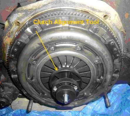
Flywheel and clutch refitted with alignment tool in place. Clutch mounting bolts must be tightened gradually and from alternate sides to prevent distortion of clutch pressure plate
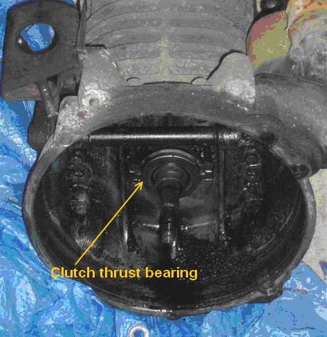
While the gearbox is out it is a good idea to replace the input shaft oil seal located behind the thrust bearing. Remove and unclip the thrust bearing, remove the three bolts holding the triangular plate and remove to reveal the seal behind. The seal can be removed using a screwdriver gently tapped into the old seal and levered out. Fit the new seal and replace the triangular cover and secure with the three bolts.
Ensure that when the thrust washer is replaced it is clipped correctly to the two operating arms by the two springs fitted. Apply Moly grease sparingly to the input shaft and spline ready for refitting.
Gearbox thrust bearing in place
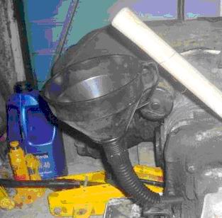
Refilling gearbox with EP80/90 Hypoid oil 4Litres (4.5 Litre can of oil available from Screwfix £13 approx)
Reinstalling engine
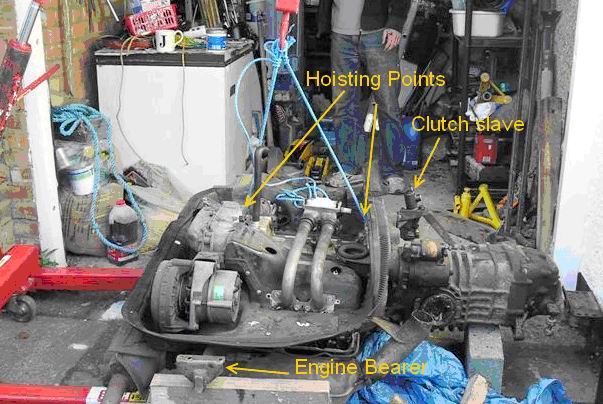
Engine and gearbox supported by hoist ready for refitting into van, with new clutch slave cylinder fitted.
Engine hoisted back into van and manipulated to avoid damaging CV joints and finally secured to chassis (bolts and nuts secured with Loctite).
Summary
Once the components and wiring had been reconnected the engine was started with the van still on the ramps after checking that the gearbox was definitely in neutral. As the van no longer uses the standard mechanical petrol pump but an electric unit we were able to prime the fuel before attempting to start the engine. I am not sure what problems might occur with a mechanical pump due to the van being on ramps. The engine started very easily but tappets very noisy but soon quietened down after about 10 minutes. Upon reflection the hoist shown is ideal for this application and we could have saved a large amount of time if we had utilised it for the engine removal. Additional helpers are essential in order to keep an eye on things when manipulating the engine.
Good Luck,
Lee
