Heater motor fan

An alchemy of sparks, copper wire and earth

Moderators: User administrators, Moderators

Jilldub
Registered user
Posts: 87
Joined: 16 Nov 2021, 19:10
80-90 Mem No: 17525
Location: Worcestershire

Re: Heater motor fan

Post by Jilldub »

Hi All.
 I have bought a new heater fan, clips, and foam kit.
 I have also purchased a PWM which has 5 wires going to the rheostat so I am able to switch it off.
There are 2 other bits attached to the PWM which are a switch for reversing the motor and a digital gauge that measures the % of power going to the motor.
I disconnected the digital gauge from the circuit board (unplugged 2 plugs) and the fan assembly mock up still works as expected.
 I noticed a small cooling fan in the PWM casing - which I am guessing comes on when the unit is running hot.
Do you think the disconnection of the digital gauge has anything to do with the units fan operation?
 I also need to buy some wire for the feed between the PWM, fan motor and power supply. Can anyone please tell me what amperage /(AWG?) wire I need to use?
 Image of PWM below Image

User avatar
Robsey
Registered user
Posts: 1171
Joined: 19 May 2012, 20:45
80-90 Mem No: 11137
Location: East Manchester

Re: Heater motor fan

Post by Robsey »

Does this help?

Image

The red/black wire to the power switch is sized at 1.0mm csa.
Personally I would increase this to 1.5mm csa to match the rest of the blower motor loom.

Are you keeping the fan switch for the on / off function.?

If so, you have got three wires of the correct size already in the van loom (As intended by VW) from the switch to the resistor pack.

Use one wire from the switch to the pwm supply + terminal. (White/black in my diagram).

The other two wires can be used to wire the load + and - wires to the motor from the pwm module
(I used yellow and yellow/black wires).

That just leaves the pwm supply - terminal, which is obviously a 1.5mm CSA brown wire straight to a metal part of the van body. Or in my case, I used one of the casing to bulkhead retaining bolts to secure the brown wire to ground - using a ring terminal.
The three wires are all 1.5mm CSA.
Last edited by Robsey on 29 Sep 2022, 22:13, edited 2 times in total.
1983 Tin Top with a poorly DF and 4 speed DT box.
1987 Electrics and a DJ engine.
Maybe one day I might get it finished

User avatar
Robsey
Registered user
Posts: 1171
Joined: 19 May 2012, 20:45
80-90 Mem No: 11137
Location: East Manchester

Re: Heater motor fan

Post by Robsey »

I had the bonus of converting our van from Torpedo fusebox to CE1 fusebox, which meant that I had a spare dash loom that I was able to cannibalise.

I have the original switch to motor loom intact in my "spares" bin should I wish to revert back to standard with the resistor pack.

From memory, the blower motors tend to come with the generic "aftermarket" wire colours of:-
Red for positive side.
Black for negative side.

As you have a reversing switch... if you get the wires the wrong way round, you could just flip the fan control to reverse.

The display will not affect the operation of the fan.
It is purely there to show you the speed as a percentage of full pelt.
I would set the speed by the "feel" of the air flow, not by a number on the dash.
1983 Tin Top with a poorly DF and 4 speed DT box.
1987 Electrics and a DJ engine.
Maybe one day I might get it finished

Jilldub
Registered user
Posts: 87
Joined: 16 Nov 2021, 19:10
80-90 Mem No: 17525
Location: Worcestershire

Re: Heater motor fan

Post by Jilldub »

Hi Robsey-thank you for coming back to me.
 I am a complete novice to vehicle electrics.
 The previous owner had drilled a hole in the plastic air distribution trim that clips to the front of the dash (just in front of the gear lever).
 I plan to leave the original on/off switch in its original position and place the new switch from the PWM into the trim panel as described.
The PWM has 5 wires going to the switch and can be switched off (there’s a positive click) so the fan motor does not rotate. Do I need another off switch? 

My plan was to tap into the original + supply to the original switch and use it to power the PWM. I was then going to run new wires from the PWM directly to the fan and from the fan back to the negative terminal of the PWM. The final wire will go from the negative power terminal on the PWM to earth.
I now think I should not use the red/black 1.0 csa wire and exchange it for 1.5 csa wire directly from fuse 13 to feed the + power terminal on the PWM.

So, in summary,
1. Is my plan to run all new wires as described above ok?
2.Bearing in mind the PWM switch has 5 wires going to it and has a positive “off” click……. Do I need a second switch to isolate power?
3. I’m not sure what 1.5 csa wire is so is there an amperage rating for it?

As always…….. Thank you for your help.


User avatar
Robsey
Registered user
Posts: 1171
Joined: 19 May 2012, 20:45
80-90 Mem No: 11137
Location: East Manchester

Re: Heater motor fan

Post by Robsey »

1.5mm csa (cross sectional area) is rated at 16 to 21 amps, dependent upon construction.

Ideally the wire should be rated at or above 20 amps.

Look here for a guide.

https://www.electricalcarservices.com/c ... -0-168-169

I am not sure why you have 5 wires...
Hard to tell without the exact details from your module.
Normally it is written in Chinese, which I am not able to understand.

Normal is 4 wires.

Supply voltage and ground return.
And
Fan out and return.
1983 Tin Top with a poorly DF and 4 speed DT box.
1987 Electrics and a DJ engine.
Maybe one day I might get it finished

Jilldub
Registered user
Posts: 87
Joined: 16 Nov 2021, 19:10
80-90 Mem No: 17525
Location: Worcestershire

Re: Heater motor fan

Post by Jilldub »

Robsey.
Thank you for your advice and the link.
I shall order and use 1.5 csa 21amp wire.

User avatar
Robsey
Registered user
Posts: 1171
Joined: 19 May 2012, 20:45
80-90 Mem No: 11137
Location: East Manchester

Re: Heater motor fan

Post by Robsey »

You thread prompted me to sort out my own PWM module.

Taken from another thread...

UPDATE - I have long since converted the van electrics to suit a more efficient PWM (pulse width modulation) motor controller on the blower motor.
Rather than big wasteful ceramic resistors in the resistor pack.
There is a video somewhere of me testing it a year ago....
https://youtu.be/H4rfR-PjSRI

Typical for me, I had purchased a module with the rheostat built into the front.
A total bugger to mount.

Image

Tonight I desoldered the rheostat from the circuit board and fitted a 12" (30cm) flying lead to improve my range of options to mount the rheostat.

Image

Image

I have put some sleeve around the rheostat to protect it from any shorts or accidents.

Et voila....

Image
1983 Tin Top with a poorly DF and 4 speed DT box.
1987 Electrics and a DJ engine.
Maybe one day I might get it finished

Jilldub
Registered user
Posts: 87
Joined: 16 Nov 2021, 19:10
80-90 Mem No: 17525
Location: Worcestershire

Re: Heater motor fan

Post by Jilldub »

Hi Robsey.
That’s a very smart job!
Obviously done by a true professional.
 I will post a few photos of mine when I get around to installing the motor.
As always…. Thank you for supporting myself and others with our electrical problems!
 

mariner
Registered user
Posts: 379
Joined: 05 Jul 2011, 20:04
80-90 Mem No: 9916
Location: Bristol

Re: Heater motor fan

Post by mariner »

Robsey wrote: 22 Sep 2022, 18:02 Looking at your first post...

I am assuming that you have checked all the obvious.
Or has the previous owner already reported a dead fan?

Fan not working.
On some speeds, or none of the speeds.

Some speeds - just top speed = resistor pack failure.

All speeds - testing order...
1 - Fuse is present, intact, and clean.
2 - Are you getting 12 volts at the "30" terminal of the fan switch.?
3 - when removed - can you turn the fan by hand.?
(Power off / take ignition key out).

Reading through this thread as my fan blows a fuse when on top speed and windscreen wipers running concurrently. Can anyone tell me what resistor pack failure means? Does this mean I may get away with a repair that doesn't involve taking off the dash? i.e. switch only? Thanks
 
1985 Super Viking with Subaru EJ22 (formerly 1.9 petrol DG)
1981 air-cooled 2.0 high top

User avatar
Robsey
Registered user
Posts: 1171
Joined: 19 May 2012, 20:45
80-90 Mem No: 11137
Location: East Manchester

Re: Heater motor fan

Post by Robsey »

Okay - two halves to this really -
1 - Resistor Pack Failure.

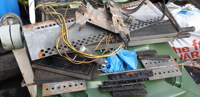
The resistor 'pack' is two resistors connected end to end, within one cylindrical body.

The barrel shaped thing with yellow wires coming from it.
Image

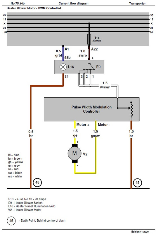
To get three speeds from your blower motor, the feed from the switch goes as follows.
Speed 1 - slowest - voltage is sent through both resistors 1 and 2 in the pack.
Speed 2 - middle speed - voltage is sent through resistor 2 only. (Bypassing resistor 1)
Speed 3 - full pelt - voltage is sent directly to the motor. (Bypassing both resistors).

Resistor pack failure is where either resistor within the pack breaks and therefore voltage cannot pass through.

Pack failure could be -
a - only speed two (not speed one) = first resistor broken.
b - neither speed one nor two = second resistor broken.
-------------------------------------

2 - Blowing fuses.
If you are blowing fuses when both blower fan and the wipers are going, it indicates that they are drawing too much current between them (too many amps).

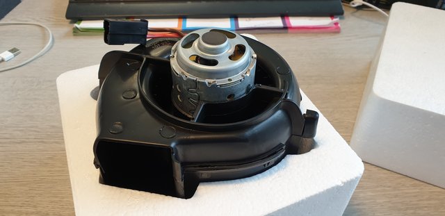
The most likely culpret would be the blower motor as these get worn or dry bearings causing stiffness to turn,
or they suffer with excess carbon build up within the motor itself.

If the blower motor is your problem, which sounds very likely, then yes it would be a dash out job to replace the motor...
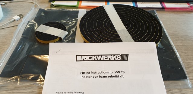
The recommendation is to refurbish the heater assembly with a fresh foam seal kit, and you will be able to see what state your resistor pack is in.

Image

Image

Then there is the catalogue of other preventitive maintenance jobs whilst the dash is out.
Clean the earth crowns, clean / check any other wiring that you can see.

Image

(I went the whole hog and rewired / converted the van from the old torpedo set-up to the later CE1 blade-fuse fuse box set-up.
Not for the faint hearted.)

As you say that both the fan and wipers are on the same fuse, I can assume you mean fuse number 10 on an early torpedo type fuse box.
1983 Tin Top with a poorly DF and 4 speed DT box.
1987 Electrics and a DJ engine.
Maybe one day I might get it finished

mariner
Registered user
Posts: 379
Joined: 05 Jul 2011, 20:04
80-90 Mem No: 9916
Location: Bristol

Re: Heater motor fan

Post by mariner »

Thanks - great reply. As I feared, it probably is a full dash out job. Will need to build up to that so in the meantime will avoid running both fan (on full pelt) and wipers together!
1985 Super Viking with Subaru EJ22 (formerly 1.9 petrol DG)
1981 air-cooled 2.0 high top

Post Reply