bigbadbob76 wrote:
Note that they suggest changing the value of the resistor between pin4 and supply to adjust for swapping to a V6 or V8 engine and the same would presumably apply to diesels with different pulley sizes.
Different No of pulses per rev depending on number of cylinders suggesting that our RV1 is frequency dependent.
Whereas their resistor between pin6 and ground is the same 191 ohm.
Although his tacho fsd is 7krpm which is slightly confusing but will be meter current fsd dependent.
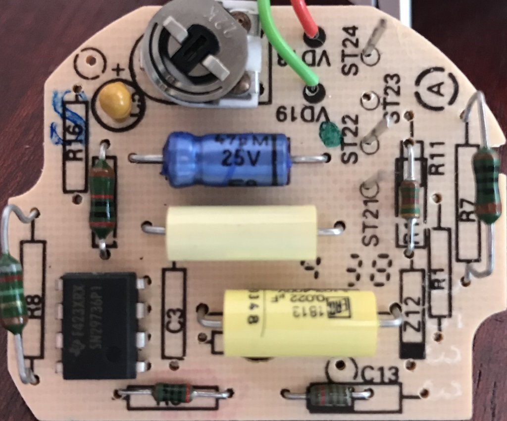
Interesting find. Yes, RV1 controls the amount that the needle swings over for a given pulse rate - it's the only adjustment available for calibrating and for 'converting' the Diesel version from one pulley size to another. So by definition it is the frequency dependent part: e.g. make the needle move half as far for a given pulse rate to convert from 4 cylinder to 8 cylinder (I think that's the right way).
I could do with some guidance on the use of the signal generator that arrived today. Two questions:
1) Power is via a small DC jack (5V, centre +ve), and it comes with a USB cable for this purpose. The output is via a BNC socket - signal on the centre pin presumably, and earth on the outer body. If I want to use this to test the tacho board, where should the signal earth go? Assuming I power the signal generator with a USB adapter, and the tacho board with a 12V supply from my bench supply, is it ok to tie the signal earth to the tacho board earth, even though the signal generator supply earth might be at a different potential? Should I run my USB adapter from the bench supply's 12V as well, just so that everything has the same earth reference?
2) My Draper multimeter has a frequency setting, and I can measure the output of the signal generator. I found I had to nudge the signal generator up to 203Hz before the multimeter said it was getting 200Hz (199.7 actually). Which one should I trust more?