I did this write up on Brickyard, but I thought it might be useful, so I've copied it over here...
Ben
-------------------------------------------------------------------------------
The analogue clock in my van’s been irritating me for a few years by randomly running fast and slow and generally being useless. Turns out it’s pretty easy and costs less than a quid to fix!
I had a brainwave and searched Google for “vanagon clock fix” and found this site - http://www.pauldottrip.com/84vanagon/an ... clock.html" onclick="window.open(this.href);return false;
Good information, but a little light on instructions, so I decided to write up how I did it. Basically you need to replace 2 capacitors and you should be good to go. If your clock is still ticking, but not keeping good time, this seems to be the cause of the problem. I’m no electronics genius, but it’s fairly straightforward. I reckon you’d be fine if you done a CDT GCSE or similar.
You will need various screwdrivers and sockets to take the instrument cluster apart, plus a soldering iron, some solder, some wire cutters and a glass to rest the clock on whilst you work on it. You also need to purchase 2 capacitors from Maplins or similar. They need to be 100μF and be suitable for over 12V. I used 2 100μF 35V Radial Electrolytic Capacitors (Maplin part number VH38R). These cost all of 29p each.
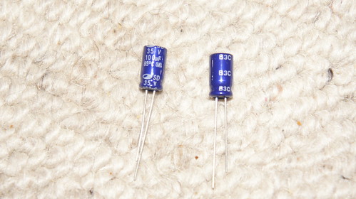
DSC01070 by ClubJoker84, on Flickr
First remove the instrument cluster from your van. It’s quite obvious how to do this. Undo the 2 screws on either side, pull off the large connector plug on the right hand side (behind the clock), unplug the speedo cable and pull out the switches. Bring it indoors.
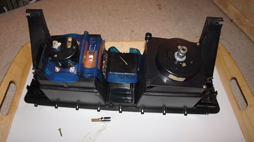
DSC01059 by ClubJoker84, on Flickr
Now remove the clock. To do this you need to move the circuit film. Pull off the white clip circled in orange in the photo. Be careful here as it holds a bit of the circuit film onto the clock contact and it is quite easy to tear the film. Undo the 5 bolts holding the film onto the back of the clock (2 above and 2 below the clock). Undo the 6 screws circled in the photo, 1 at each corner, 1 on top of the clock and one on the transistor on the right hand side. This will allow you to lift the clock slightly off the cluster and unclip the big black connector on the left hand side. There is a clip at the top and the bottom. These are quite stiff. Rest the clock back on the cluster and put the black connector clock to one side.
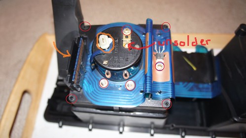
DSC01060 by ClubJoker84, on Flickr
The circuit film is held on the clock by a number of “spikes” as shown in the following photo. You need to prise the film off these very carefully. I used a small screwdriver to do this. The film can now be lifted away from the clock and the clock removed. Put it face down on top of the glass so you do not damage the hands.
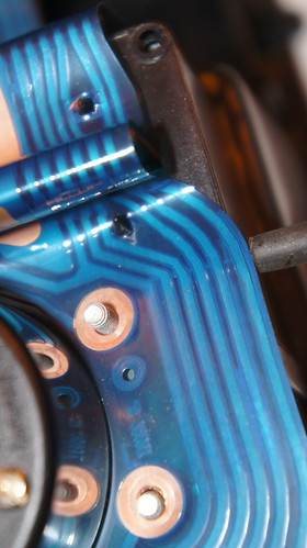
DSC01061 by ClubJoker84, on Flickr
Next step is to remove the temperature and petrol gauges. These are simply clipped in place. Just squeeze the clips to remove them. Set them down carefully as the needles are delicate.
DSC01064 by ClubJoker84, on Flickr
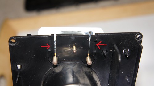
You will be left with the clock mechanism in its case. With it face down on top of the glass, you will see that it is held in by 3 small screws at the back of the case and 3 around the front. It is also held by a solder connection marked “unsolder” in the first picture. Unsolder this before undoing the screws. You can get unsoldering tools that suck the solder away, but I’m too tight to buy one of these. I did it by prising up the copper connector whilst I heated up the solder. Once the solder is molten, the copper contact will just lift off. Undo the 3 screws front and back and you should be able to lift the plastic casing off.
DSC01065 by ClubJoker84, on Flickr
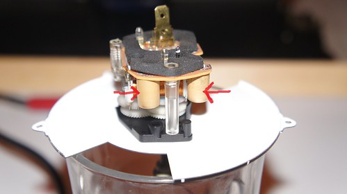
Turn the mechanism around until the 2 gold cylinders underneath the board are facing you. These are the capacitors that you need to replace. Pull off the foam backing on the circuit board. You need to unsolder the two capacitors. You will see their “legs” sticking up through the board as circled in the photo. Either use your unsoldering tool or prise them off whilst you heat the solder.
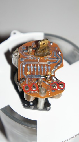
DSC01067 by ClubJoker84, on Flickr
Clear out the holes in the board. Take your new capacitors and poke them through the holes. Note that one leg is longer than the other. The long leg is the +ve side and needs to go through the hole marked +ve. On mine these were on the left as you looked at the board. Solder them in and snip off the excess.
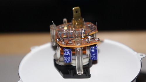
DSC01071 by ClubJoker84, on Flickr
Reassembly is the reverse of the disassembly. Put the foam back in place, put the plastic case back on the back and screw it in place. Resolder the contact on. Clip the fuel and temperature gauges. I gave the needles a clean at this stage – big difference! Put the circuit film back on and replace all the screws and nuts. The big black connector block can now be clipped back on. You need to be very careful when you put the white connector back at the rear of the clock. It is easy to crease the circuit board. Put the instruments back in the van, reconnect switches, speedo etc. and enjoy perfect timekeeping.


