bigbadbob76 wrote:It's not something I've ever done TBH.
I still don't see how to avarge out the duty cycle to produce a voltage, that's calculus teritory.
Area under the graph and all that.
If the peak voltage is constant then the avarage current must change, possibly using an inductor to smooth it would work but I'm in the dark I'm afraid.
E D I T- you could try looking at frequency to voltage converter chips, I did use one years ago in a 400Hz servo system but that's probably obsolete now.
Sorry Bob - that was my poor attempt at humour - it wasn't a dig at you.
If I was going to use this as my primary means to measure RPM or speedo rate, then it would be convenient to only have to make a single voltage measurement, so then the challenge would be to average/smooth those pulses electrically. Without that it just means I have to sample the voltage for a couple of cycles and make a numerical average. But that's doable, so it's not worth wasting any time on an electrical equivalent.
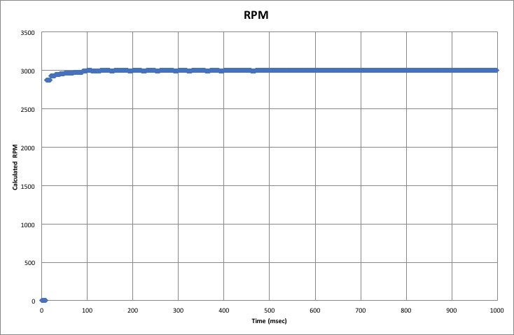
But I've been doing some quick tests with a file of 100Hz samples that I recorded on the Arduino from the signal generator. And it seems that a very simple algorithm that 1) spots the rise and fall times of a pulse, 2) averages them to get the mid-point, leads very quickly to a good estimate of RPM.
Here's a chart of calculated RPM, based on a running average of the time between pulses. You can see that it reaches a very good estimate of the engine speed within 100ms, so one tenth of a second.
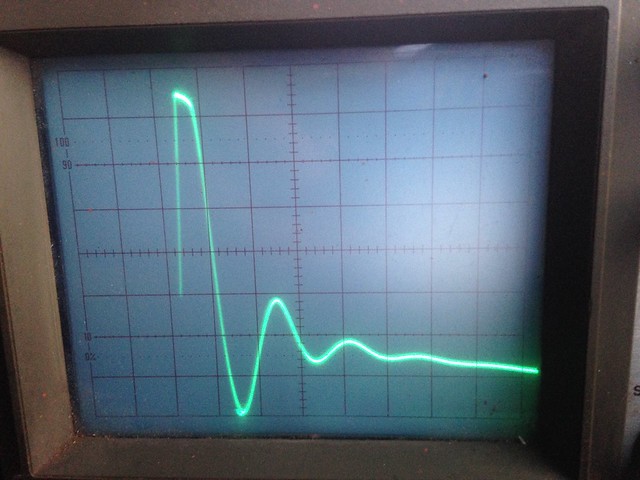
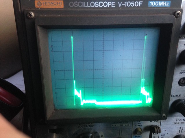
So I think this would be my preferred method. I'll have another go at capturing real coil pulses this evening. I'm puzzled why the pulses on pin 2 are at such a low voltage (~0.25V). Given that they've been through a 5V6 Zener diode, shouldn't they be at 5.6V? For a future implementation it would be good to not have to rely on a tacho board to get these pulses into the Arduino, so some kind of simple conditioning circuit, like the input part of the tacho board, would be ideal. According to the tacho circuit, the coil pulses pass through R7 (33k), and the 5V6 Zener to get to pin2, and there's a 3.2nF capacitor and R3 (3k3) in parallel linking the zener input to GND. Would this be sufficient as an input stage for the Arduino? What would I change to safely get the voltage up a bit?