
How big should this 22 Ohm resistor be on the regulator ground pin? My poor knowledge of electrical circuits is letting me down, and I don't know how to work out the power rating.
If it's only lifting the ground pin by a small amount above 0V, say 1V (how much is a small amount?) then the power through that resistor is V*V/R = 45mW. But on the other hand, if the current through the regulator is the sum of the gauges (0.1A + 0.1A, higher perhaps when the gauges' resistance changes?), then power through the resistor would be I*I*R = 0.88W. Two vastly different numbers, one trivial and one quite significant, and I don't know whether either is correct. How big is the original?
Replacing the dashboard plastic PCB
Moderators: User administrators, Moderators
Re: Replacing the dashboard plastic PCB
"I'm a man of means, by no means....King of the Road!"
1983 Viking Xplorer, 2.1DJ
1983 Viking Xplorer, 2.1DJ
-
CovKid

- Trader
- Posts: 8409
- Joined: 30 Apr 2006, 13:19
- 80-90 Mem No: 3529
- Location: Ralph - Coventry (Retired)
- Contact:
Re: Replacing the dashboard plastic PCB
As far as I know, 1/4 watt. If you want to lean on the safe side: https://www.electronics2000.co.uk/calc/ ... ulator.php" onclick="window.open(this.href);return false;
Roller paint your camper at home: http://roller.epizy.com/55554/" onclick="window.open(this.href);return false; for MP4 download.
Re: Replacing the dashboard plastic PCB
Thanks Ralph - I know the formulae, but it's the input values I'm not sure of. If the original is a 1/4W, that suggests they've simply used the smallest common size above the lower value from the first of my two calculations. If it's the same size as the LED current limiting resistors, then it's a low power one - if it's the same size as the alternator resistor(s), then it's higher power.
"I'm a man of means, by no means....King of the Road!"
1983 Viking Xplorer, 2.1DJ
1983 Viking Xplorer, 2.1DJ
-
CovKid
- Trader
- Posts: 8409
- Joined: 30 Apr 2006, 13:19
- 80-90 Mem No: 3529
- Location: Ralph - Coventry (Retired)
- Contact:
Re: Replacing the dashboard plastic PCB
I think I'd go one size up to cover yourself. I shouldn't think the price difference is much.
Roller paint your camper at home: http://roller.epizy.com/55554/" onclick="window.open(this.href);return false; for MP4 download.
Re: Replacing the dashboard plastic PCB
I'd prefer a more reasoned approach. What if I go up one size from 0.25W to 0.5W, and it turns out that my I*I*R=0.88W calculation is correct?
There's room on the board for a 10mm resistor, but no point going overboard if this resistor only has to handle few 10s of milliwatts.
There's room on the board for a 10mm resistor, but no point going overboard if this resistor only has to handle few 10s of milliwatts.
"I'm a man of means, by no means....King of the Road!"
1983 Viking Xplorer, 2.1DJ
1983 Viking Xplorer, 2.1DJ
-
AngeloEvs

- Registered user
- Posts: 1345
- Joined: 22 Nov 2007, 19:22
- 80-90 Mem No: 4709
- Location: Upwell, Norfolk
Re: Replacing the dashboard plastic PCB
1/4 watt is fine, as VW fitted.
1987 DG Karisma LPG with remodelled interior
Re: Replacing the dashboard plastic PCB
Thanks Angelo.
"I'm a man of means, by no means....King of the Road!"
1983 Viking Xplorer, 2.1DJ
1983 Viking Xplorer, 2.1DJ
Re: Replacing the dashboard plastic PCB
My boards arrived today. Ordered Sunday evening, in my hands Friday afternoon. I doubt that could be beaten even with an express service, and that's their standard service, and shipped from the other side of the world.
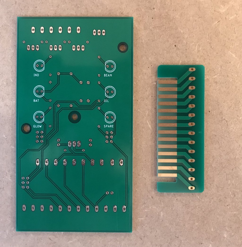
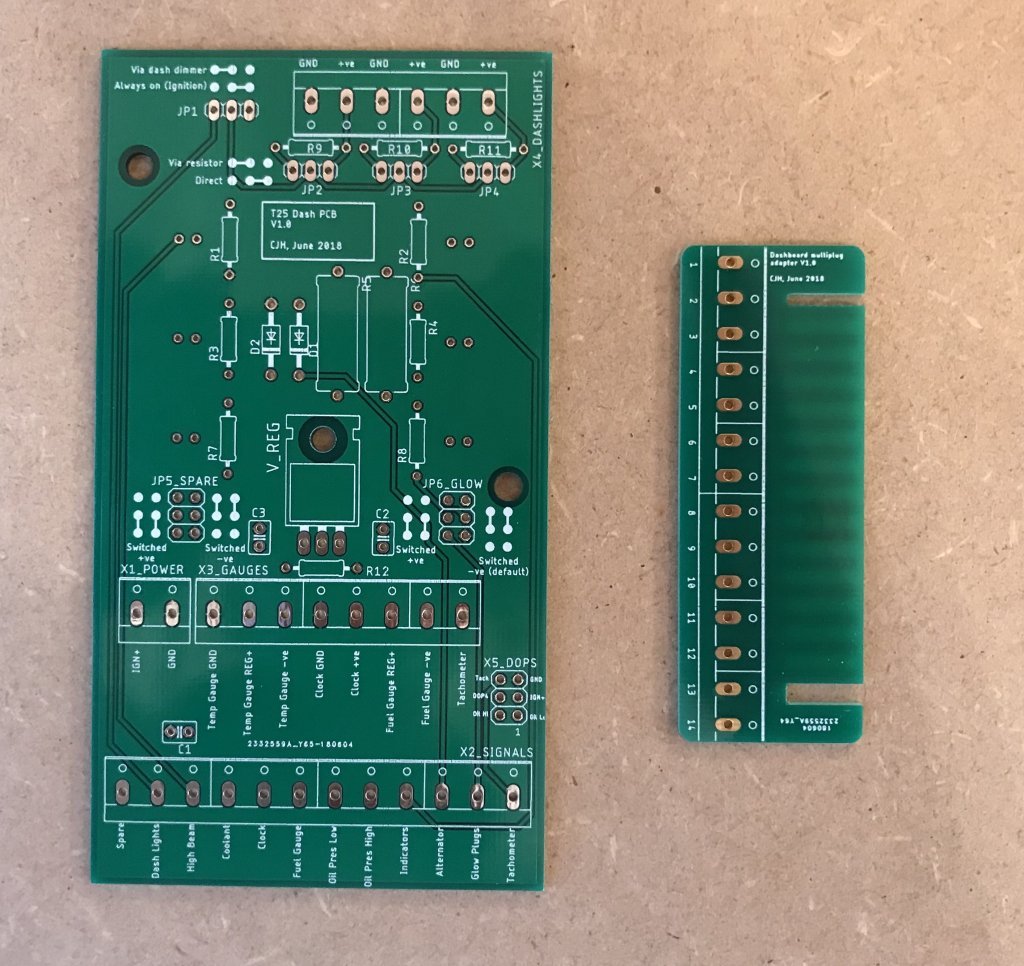
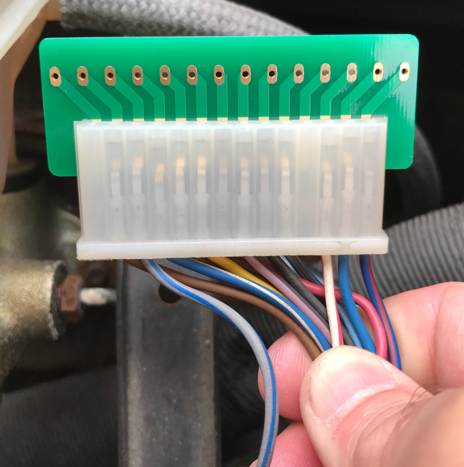
So of course I've been trying them out. The multiplug adapter board is a nice tight fit, as intended.

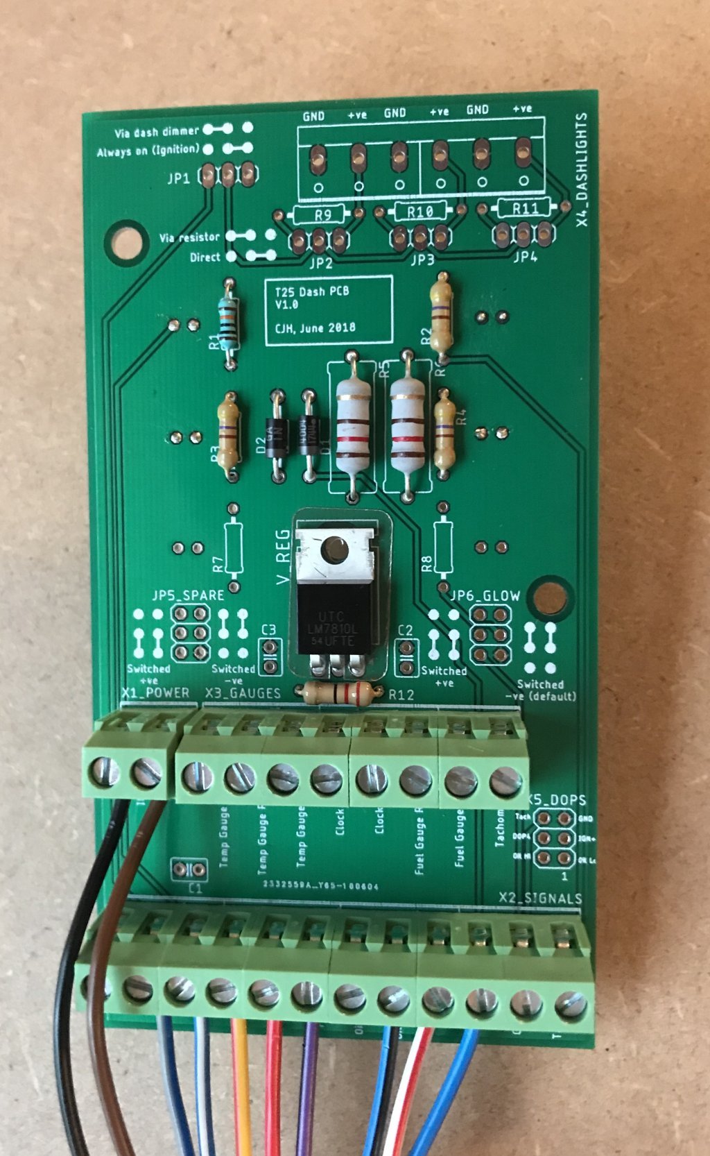
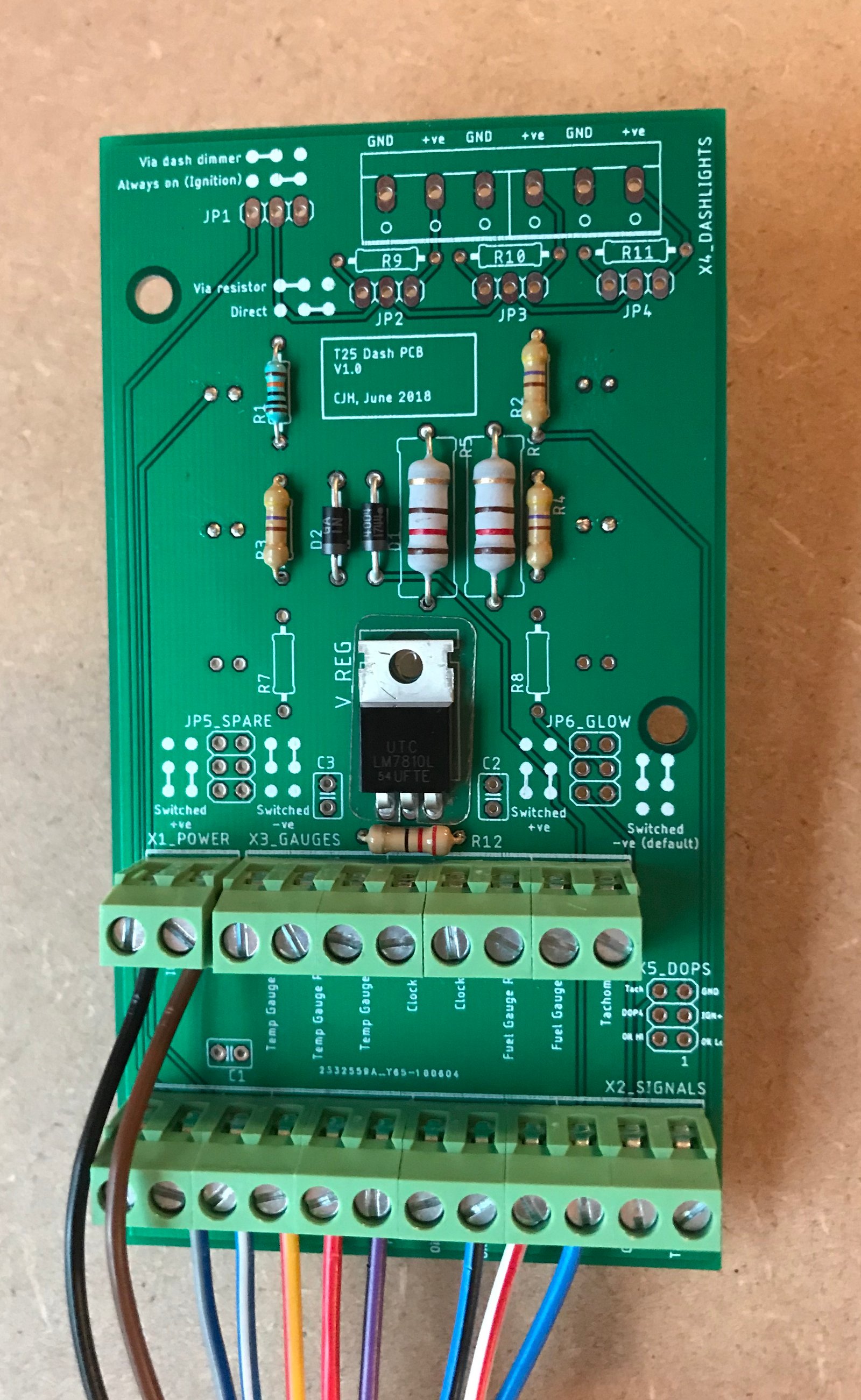
I've started to build one up with the bare minimum set of components for my early petrol dash. The voltage regulator is a cheapo LM8210. With the ground pin resistor shorted, and an input voltage of 12.3V, it measures 9.9V on my multimeter. With the 22 Ohm resistor in place it measures a whisker over 10V. I'm glad I reinstated the space for the resistor.
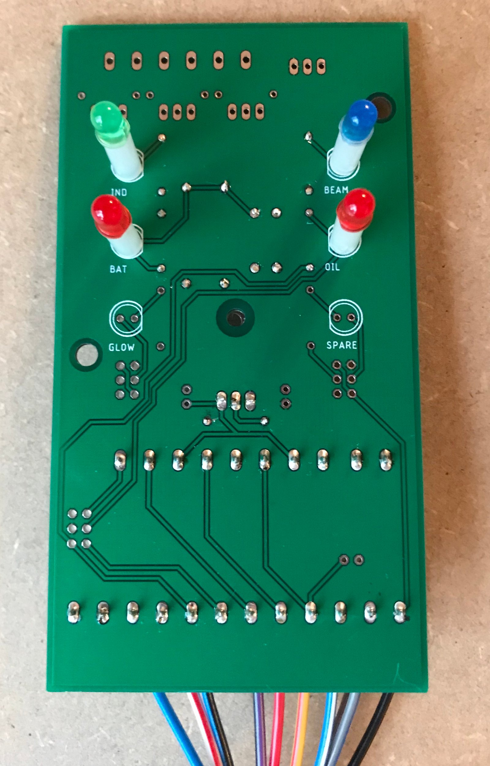
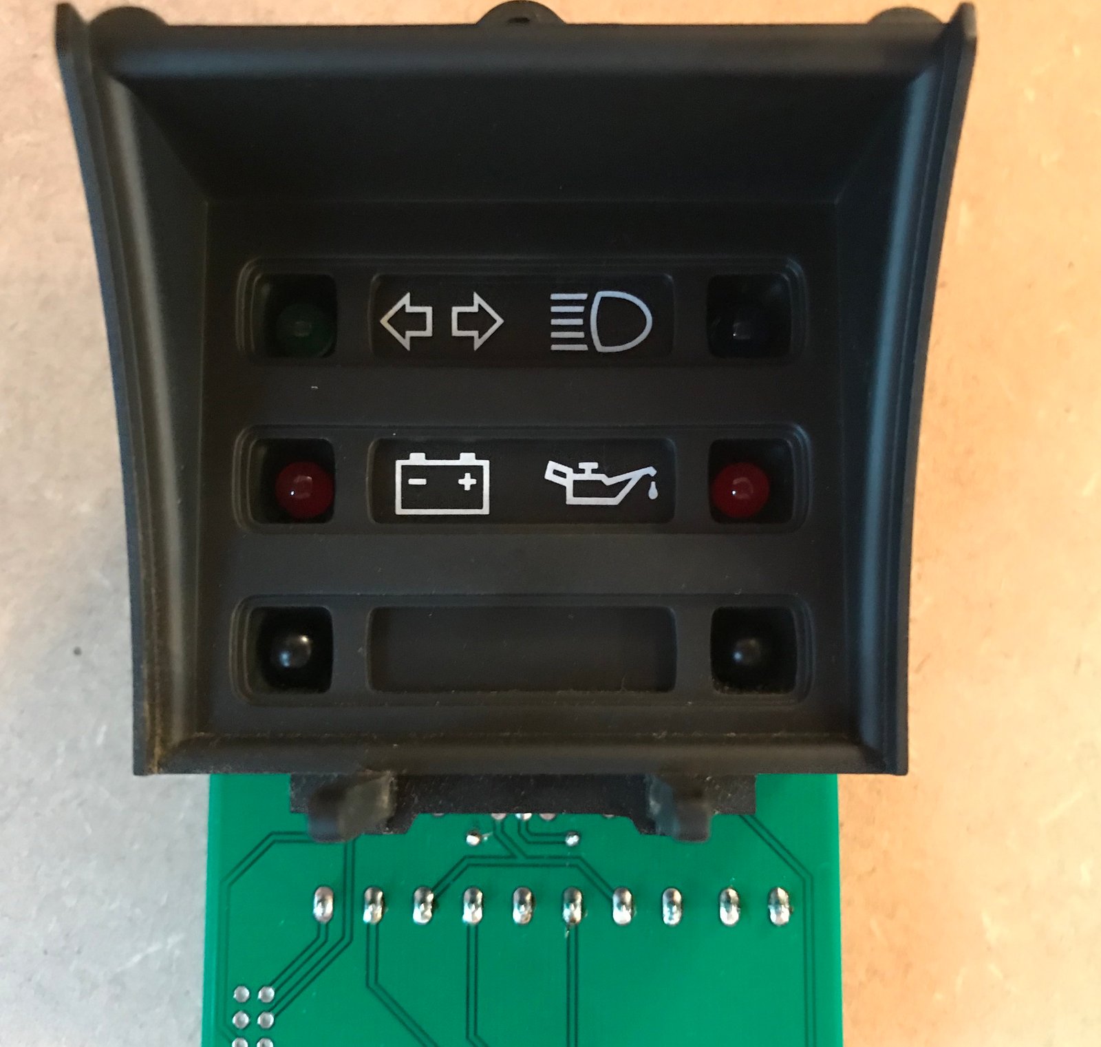
I've put the LEDs on 16mm stand-offs, and they fit the dash panel frame perfectly.
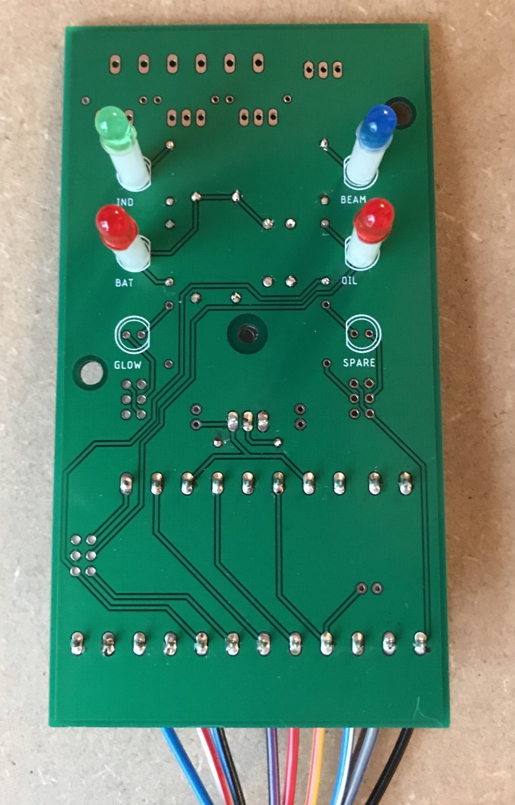
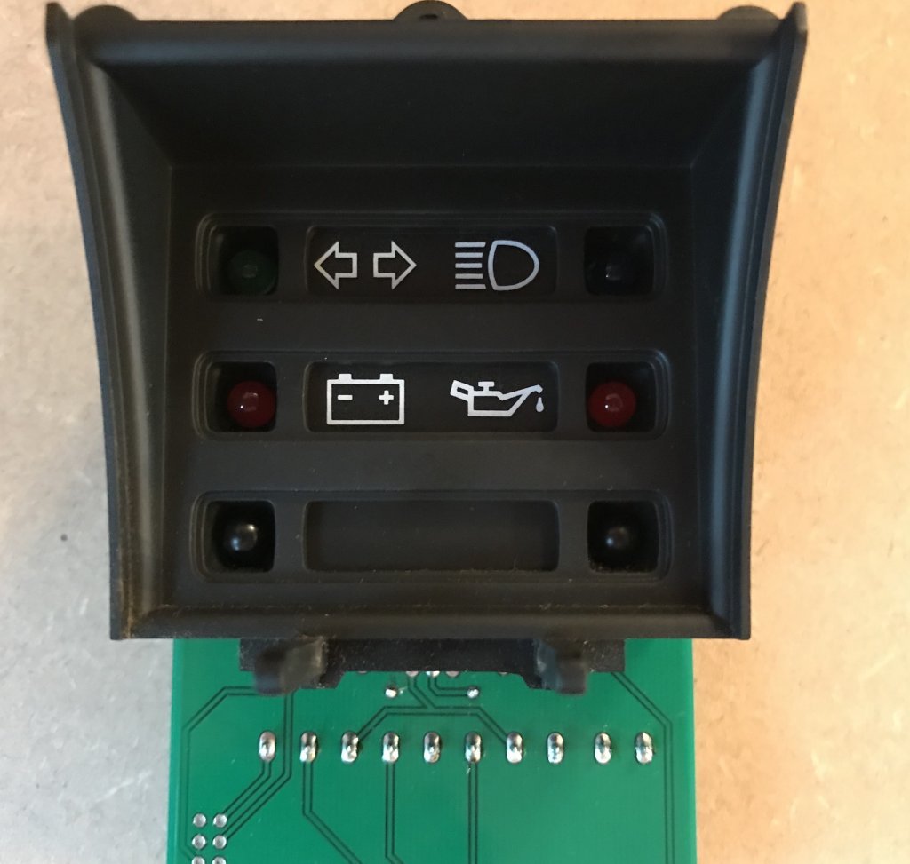
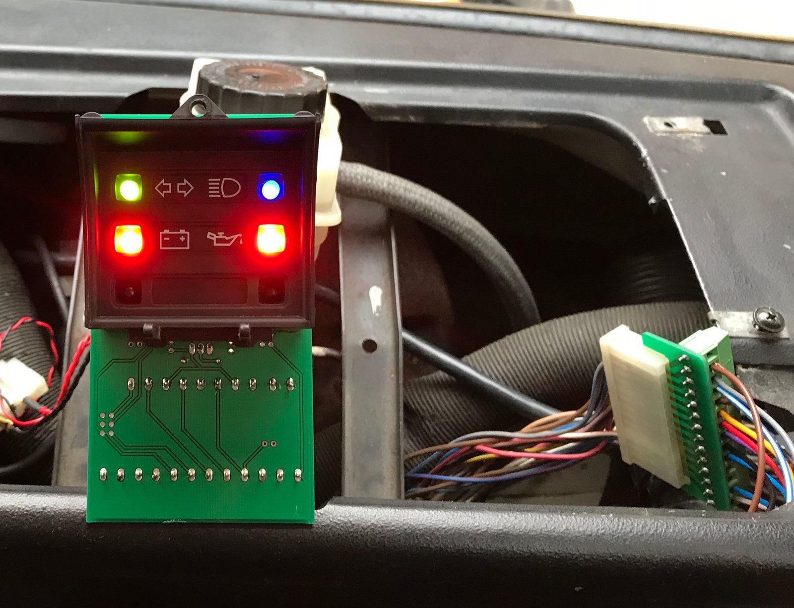
I gave this partially built setup a quick test in the van - so far so good. The red lights go off when the engine starts. The two red LEDs and the green one are using 470 Ohm resistors. The blue one is unfortunately rated as the brightest of all of them, so I've started with a 100k resistor to make sure it isn't too bright. Will test it this evening when it gets dark.

The soldered terminals on the underside of the multiplug adapter will need some insulation to stop them shorting out on a bit of the dash, or the plug could just be zip tied somewhere to make sure that can't happen.
Looking forward to finishing the build tomorrow so that I can test the configurable spare LEDs, the dash light connections and the gauges connections.
Some minor niggles:
I mis-labelled the two oil pressure sender inputs - Lo should be Hi, and Hi should be Lo.
I put the header pins for the DOPS connection a tiny fraction too close to the gauges connections, and there isn't quite room for the box headers that I bought to accept a ribbon cable plug. But a standard pin header will be fine.
The screw down terminals partially obscure the labels text.
I can fix all those points in another iteration.
Oh, and I forgot to order in the right wire colour for the indicators signal.
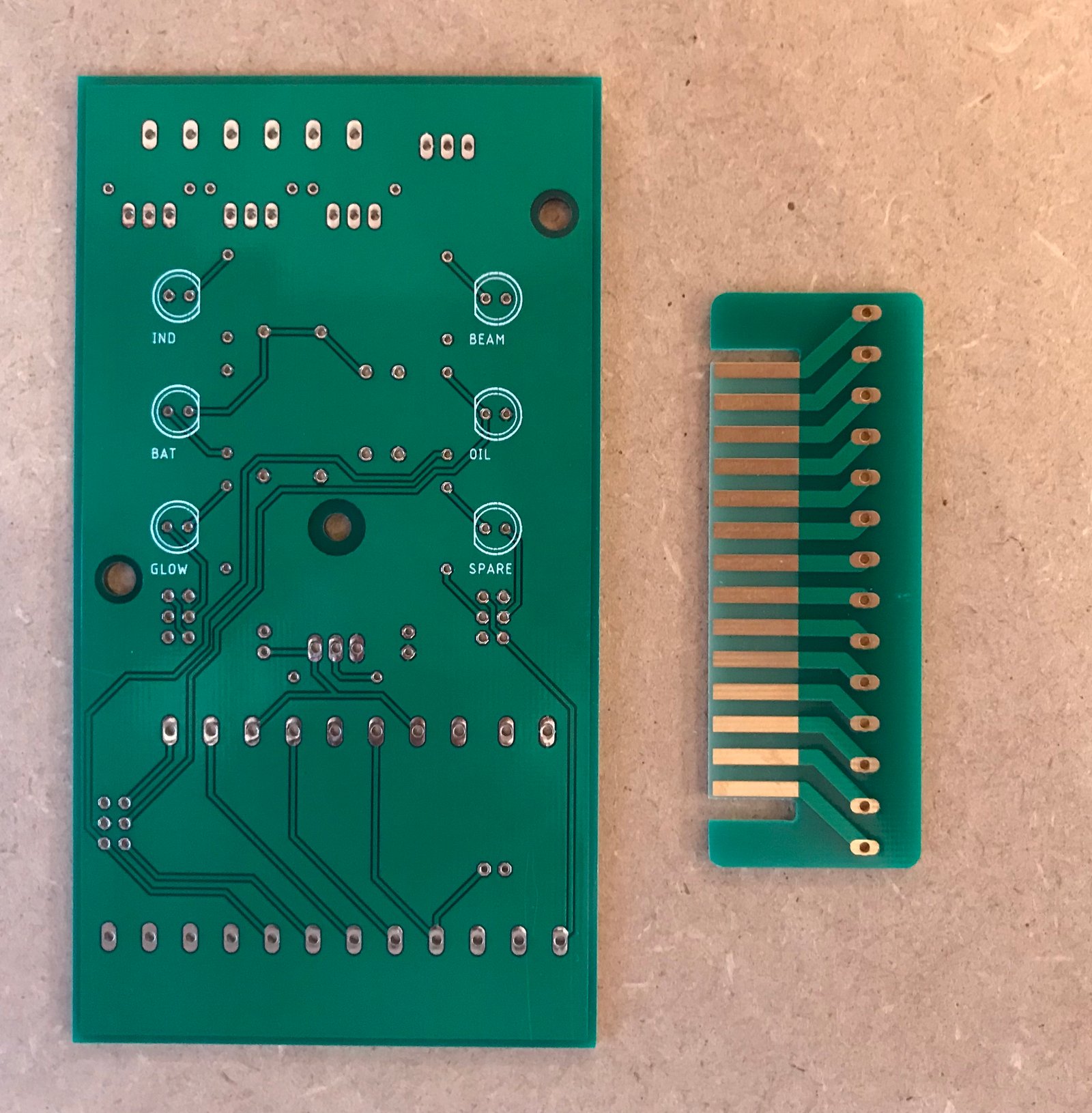

So of course I've been trying them out. The multiplug adapter board is a nice tight fit, as intended.
I've started to build one up with the bare minimum set of components for my early petrol dash. The voltage regulator is a cheapo LM8210. With the ground pin resistor shorted, and an input voltage of 12.3V, it measures 9.9V on my multimeter. With the 22 Ohm resistor in place it measures a whisker over 10V. I'm glad I reinstated the space for the resistor.
I've put the LEDs on 16mm stand-offs, and they fit the dash panel frame perfectly.
I gave this partially built setup a quick test in the van - so far so good. The red lights go off when the engine starts. The two red LEDs and the green one are using 470 Ohm resistors. The blue one is unfortunately rated as the brightest of all of them, so I've started with a 100k resistor to make sure it isn't too bright. Will test it this evening when it gets dark.
The soldered terminals on the underside of the multiplug adapter will need some insulation to stop them shorting out on a bit of the dash, or the plug could just be zip tied somewhere to make sure that can't happen.
Looking forward to finishing the build tomorrow so that I can test the configurable spare LEDs, the dash light connections and the gauges connections.
Some minor niggles:
I mis-labelled the two oil pressure sender inputs - Lo should be Hi, and Hi should be Lo.
I put the header pins for the DOPS connection a tiny fraction too close to the gauges connections, and there isn't quite room for the box headers that I bought to accept a ribbon cable plug. But a standard pin header will be fine.
The screw down terminals partially obscure the labels text.
I can fix all those points in another iteration.
Oh, and I forgot to order in the right wire colour for the indicators signal.
"I'm a man of means, by no means....King of the Road!"
1983 Viking Xplorer, 2.1DJ
1983 Viking Xplorer, 2.1DJ
-
MidLifeCrisis
- Registered user
- Posts: 566
- Joined: 20 Nov 2011, 19:07
- 80-90 Mem No: 10519
- Location: Bagshot, Surrey
Re: Replacing the dashboard plastic PCB
That is pretty spot on!!
You have created a little piece of genius there - very nice job!!
I think this sort of project is the reason that this forum is as good as it is!!
10 out of 10 !!!

You have created a little piece of genius there - very nice job!!
I think this sort of project is the reason that this forum is as good as it is!!
10 out of 10 !!!
1987 Westfalia Van, Petrol 2.0 AGG
Re: Replacing the dashboard plastic PCB
That's kind of you to say, but of course we all know where this thread started. Covkid's original work, and your idiot-proof diagrams showed the way.
100k is just right for the high beam as it turns out.
100k is just right for the high beam as it turns out.
"I'm a man of means, by no means....King of the Road!"
1983 Viking Xplorer, 2.1DJ
1983 Viking Xplorer, 2.1DJ
-
CovKid
- Trader
- Posts: 8409
- Joined: 30 Apr 2006, 13:19
- 80-90 Mem No: 3529
- Location: Ralph - Coventry (Retired)
- Contact:
Re: Replacing the dashboard plastic PCB
What I like about it Chris is although I switched to an ATX plug to connect loom to dash, I could still wire this up even without the original plug. Mind you, the main reason I switched to an ATX is it provided a greater number of connections, but to be honest I think you've covered it all.
Roller paint your camper at home: http://roller.epizy.com/55554/" onclick="window.open(this.href);return false; for MP4 download.
Re: Replacing the dashboard plastic PCB
Yes, certainly, anyone who's already implemented an alternative to the factory multiplug should still be able to connect up to the LED board, and will have no need of the 'fingers' multiplug adapter. And in terms of additional connections, I've tried to make the inputs to the LED board a superset of everything on any of the different dash configurations (so the same board should work for all models), plus there's an extra input to run a 6th LED if you have something else you need a dash warning light for.
One of my aims is to make this flexible, so there aren't separate PCBs for diesel/petrol, early/late etc. But I've only got an early petrol dash (with a retro-fitted time clock), so I can't be certain that I've covered all the options - I'm open to suggestions for the next iteration.
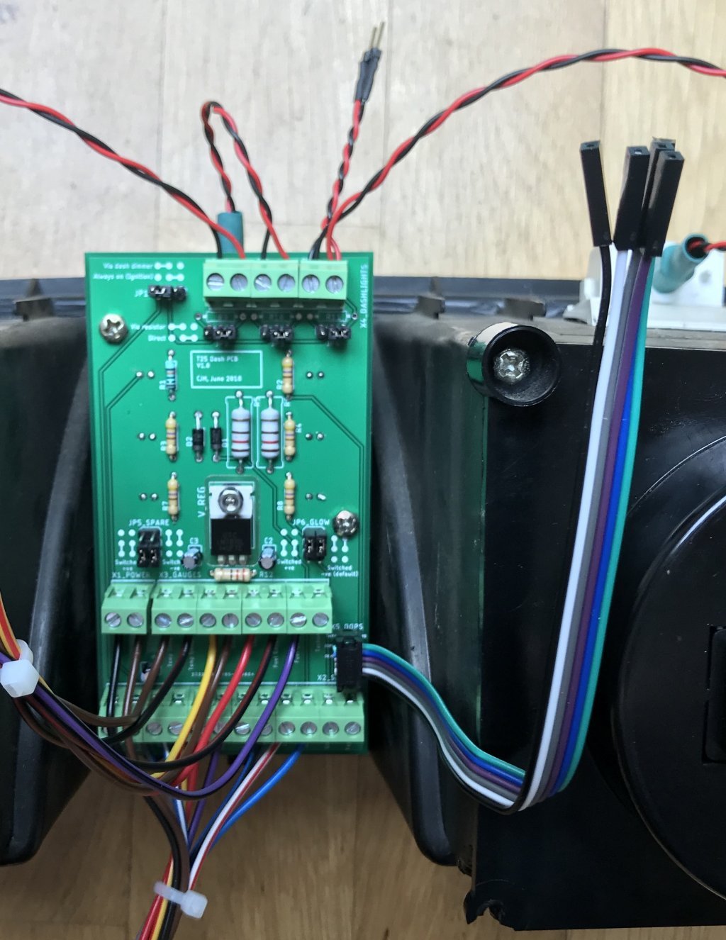
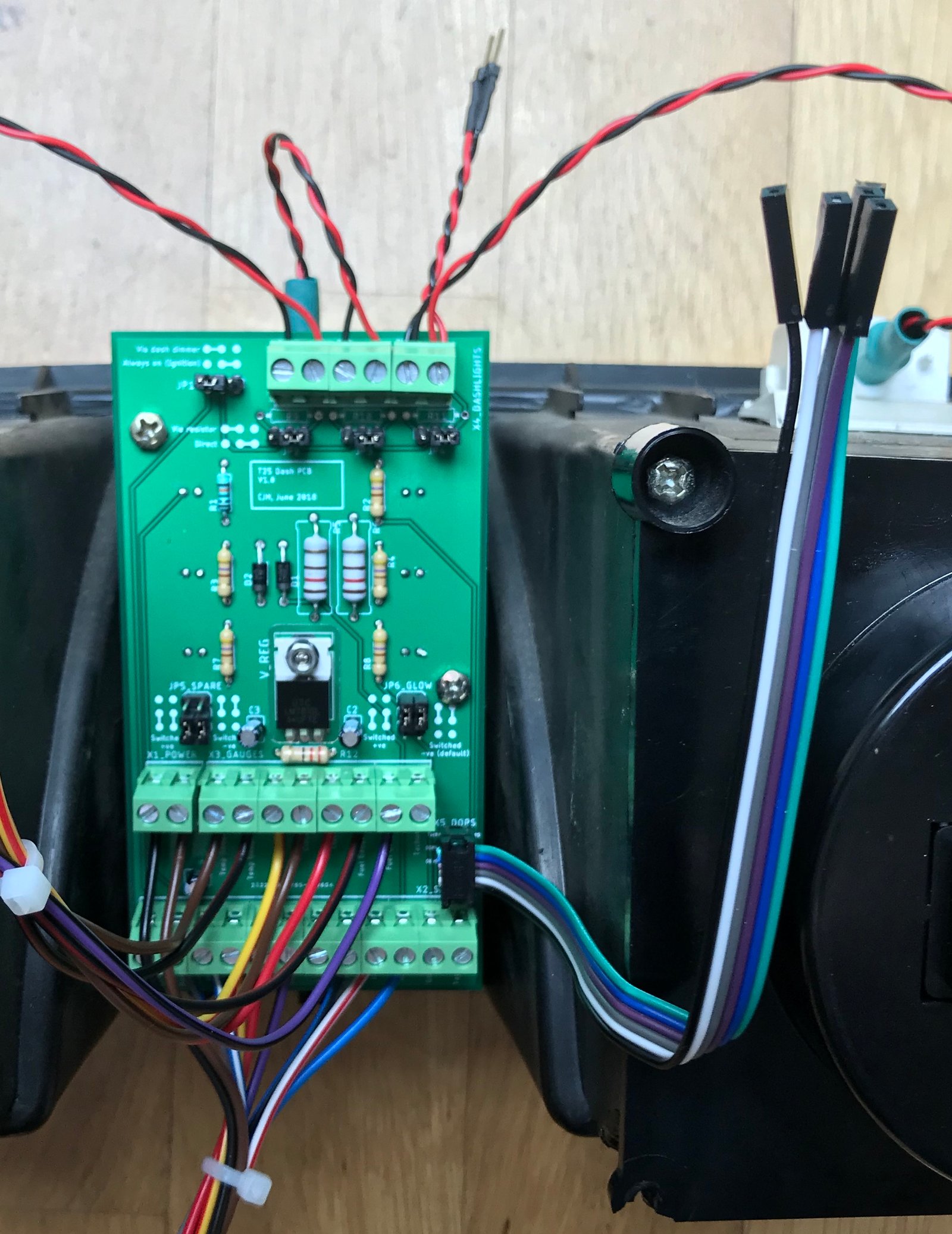
I've finished building mine up this morning. Some more photos.
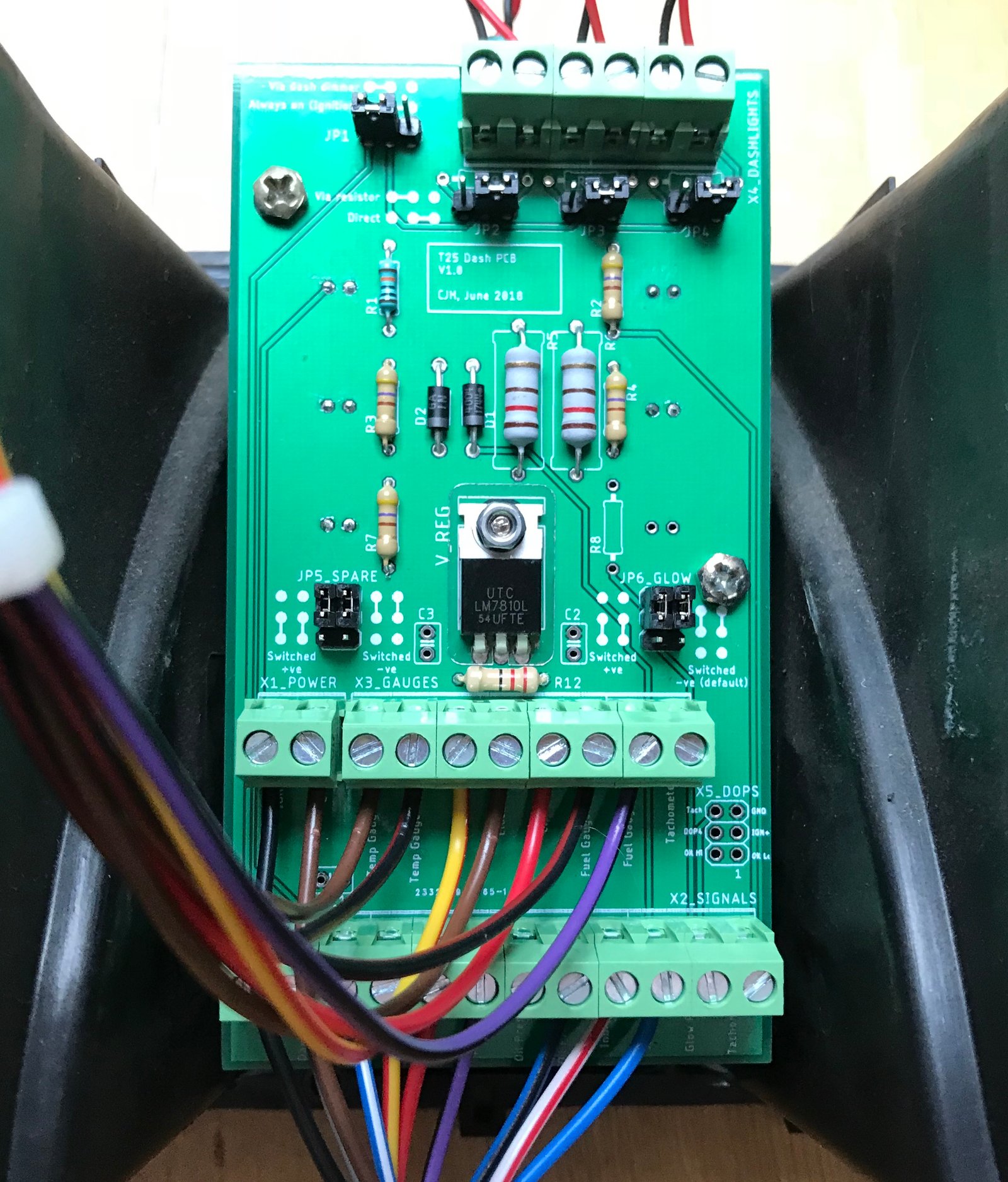
Here's an overview. I've used dimmable 0.2W LEDs as the dash illumination bulbs. I struggled to find a suitable wired bulb socket, so in the end I bought standard replacement bulbs and soldered wires onto the terminals.
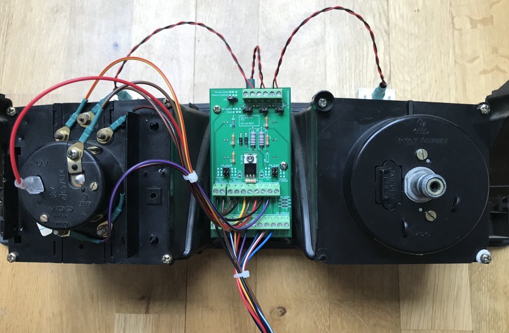
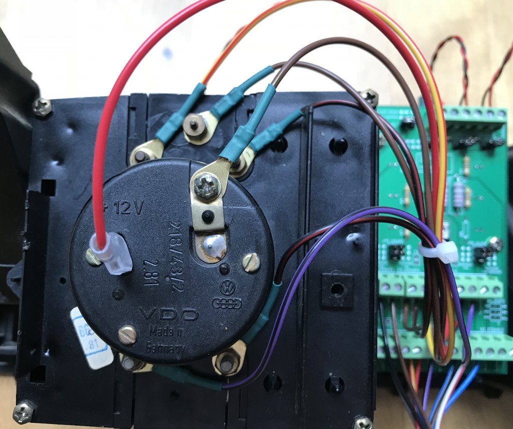
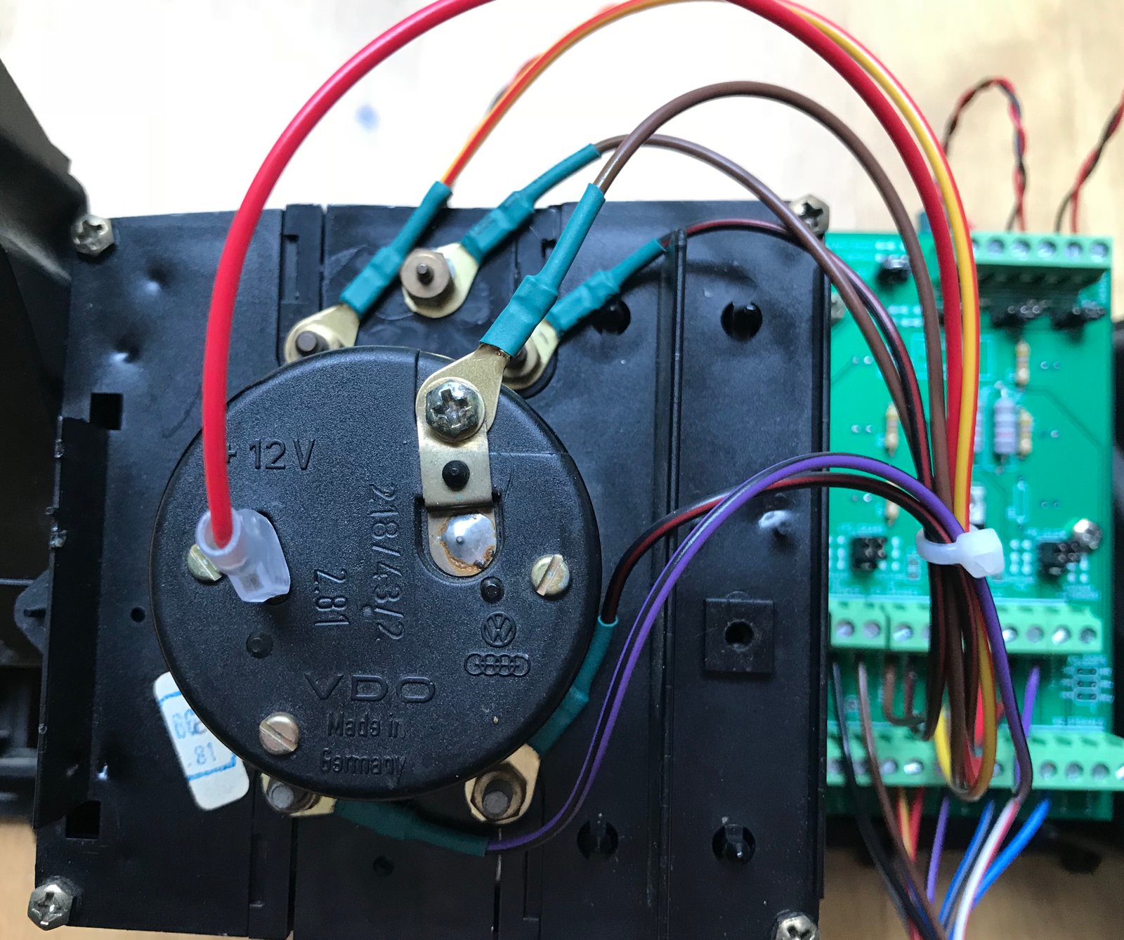
Here's the gauges wiring. There is no 'standard' set of wire colours for these, because the original flexible circuit board didn't use wires, but I stuck to the colours used for the corresponding connections on the multiplug, and added black/red as my 'regulated 10V' colour.
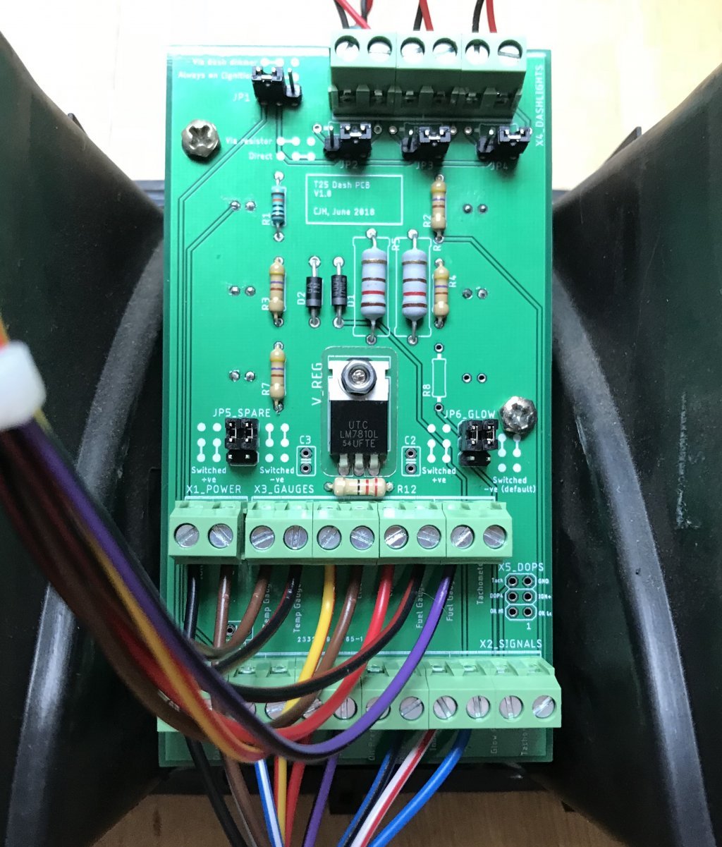
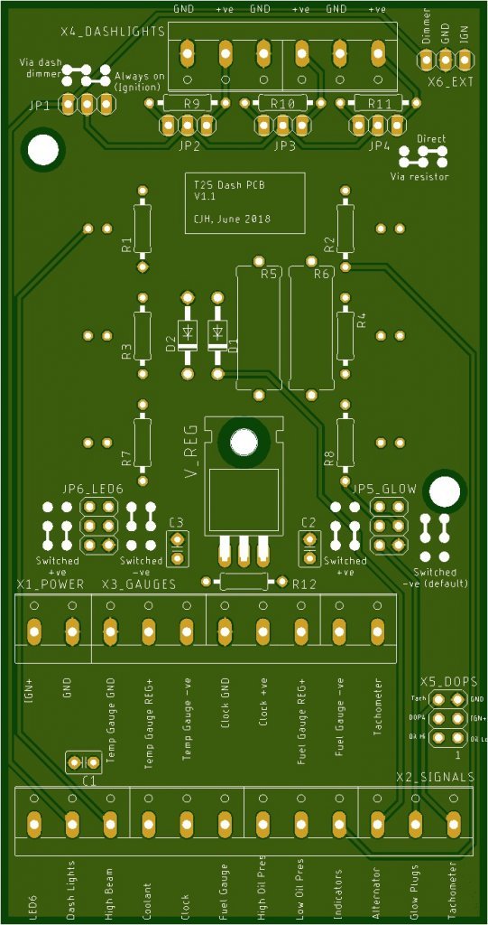
Here's the built-up PCB. I put a yellow LED in the 6th (unused) dash slot so I could test the jumper options. Since I have a petrol dash I could have used the glowplugs LED slot as a spare as well, but I'm struggling to think of a use for one spare, never mind two. I haven't yet fitted any of the capacitors - one is for the clock supply (not present on my original 'early' flexible circuit board I believe) and the other two are to provide 'optimum stability' for the 10V regulated supply. I'll see how the dash behaves for a while then fit the capacitors and see if anything changes.
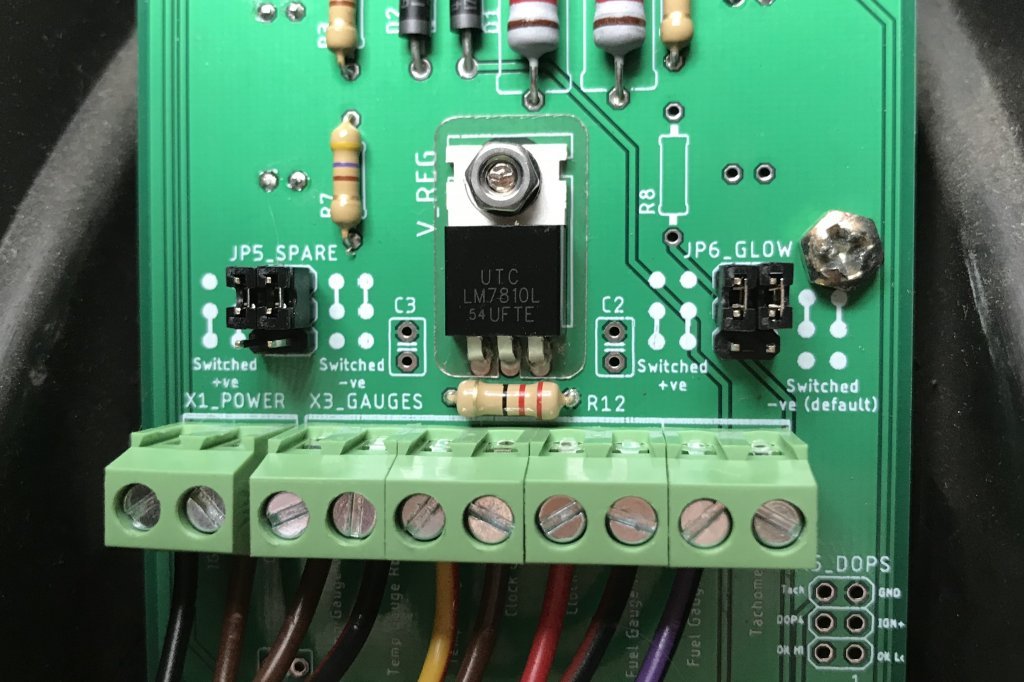
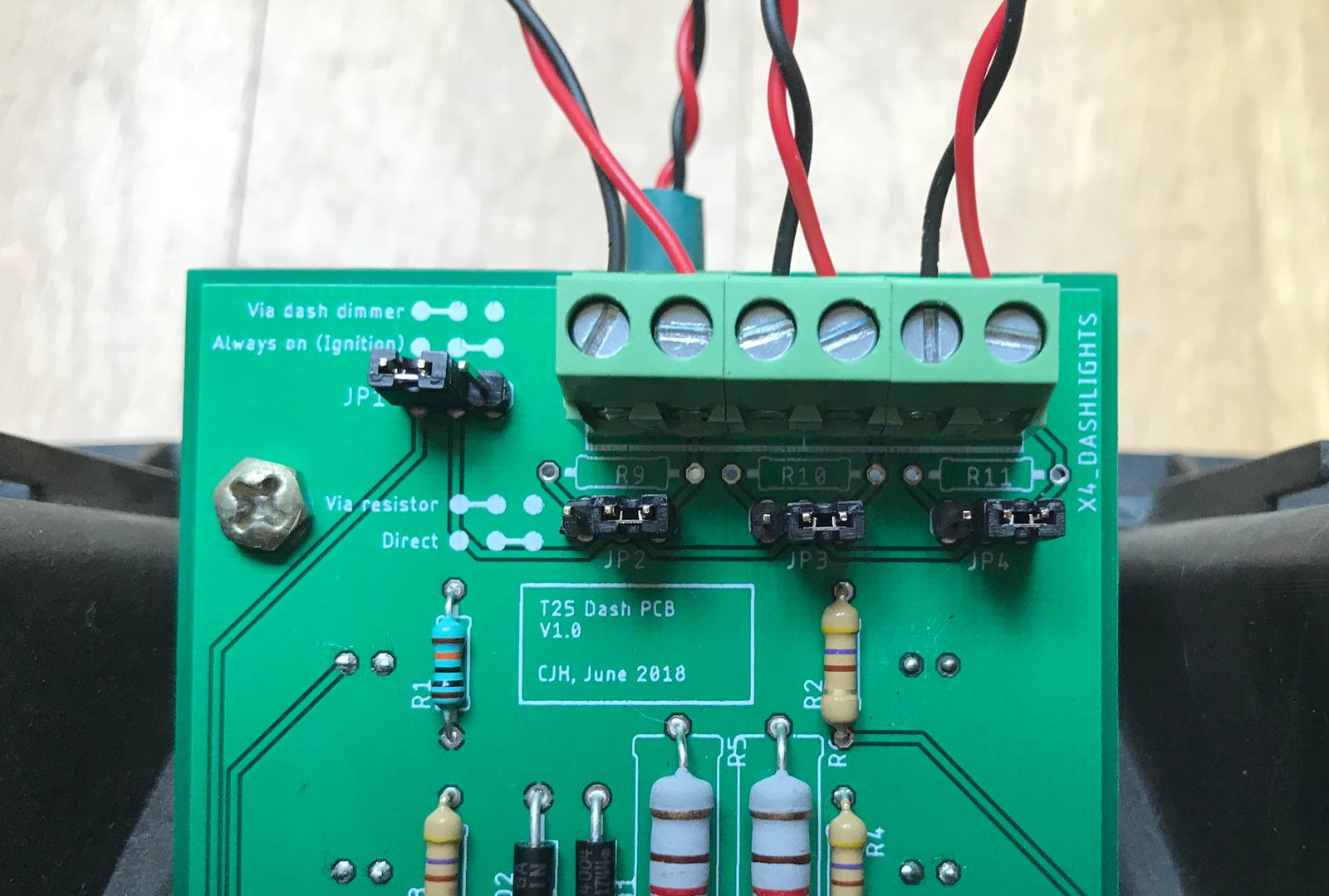
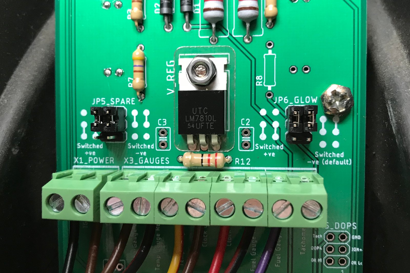
Here's a close-up of the jumpers for the glowplugs and 'spare' LEDs. They're both configured as 'switched -ve' at the moment, which means the LED will light when the input signal is grounded. In the other jumper positions they will light when the input signal goes to +12V. The jumpers have to be set as a pair - if you mix them up the LED either does nothing or stays on all the time.
Here'a close-up of the dash illumination jumper setup.
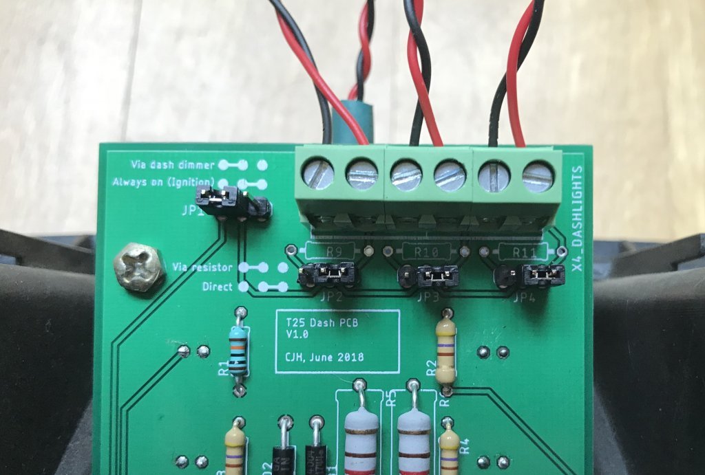
The top-left jumper is set so that the lights feed comes from the dashboard dimmer, so they'll only come on with the vehicle lights, and they can be dimmed if your bulbs allow that. The other setting takes the lights feed directly from ignition live, so that they're on whenever the ignition is on, and they can't be dimmed. The other three jumpers are set so that the bulbs are fed with all the current the feed can supply - that's because I'm using 12V LED bulbs. If you want to use low voltage/low current LEDs, the jumpers can be set to pass the source through current limiting resistors R9, R10 and R11. I haven't populated those resistor positions on this board - no point with my 12V LEDs.
 .
.
I connected up to my van's multiplug - nothing went bang, and it all seems to work. I'll now refit the dash properly and see how it fares for a day or two. Then I'll fix the niggles and order the next iteration.
New niggles discovered today:
The LED housing fouls on the solder lugs behind the dashlights configuration pin headers - will move them a few mm up for the next version.
I found some more issues with the terminal labelling (coolant and fuel gauge terminals are incorrectly labelled as +ve) - simple fixes.
One of my aims is to make this flexible, so there aren't separate PCBs for diesel/petrol, early/late etc. But I've only got an early petrol dash (with a retro-fitted time clock), so I can't be certain that I've covered all the options - I'm open to suggestions for the next iteration.
I've finished building mine up this morning. Some more photos.
Here's an overview. I've used dimmable 0.2W LEDs as the dash illumination bulbs. I struggled to find a suitable wired bulb socket, so in the end I bought standard replacement bulbs and soldered wires onto the terminals.

Here's the gauges wiring. There is no 'standard' set of wire colours for these, because the original flexible circuit board didn't use wires, but I stuck to the colours used for the corresponding connections on the multiplug, and added black/red as my 'regulated 10V' colour.
Here's the built-up PCB. I put a yellow LED in the 6th (unused) dash slot so I could test the jumper options. Since I have a petrol dash I could have used the glowplugs LED slot as a spare as well, but I'm struggling to think of a use for one spare, never mind two. I haven't yet fitted any of the capacitors - one is for the clock supply (not present on my original 'early' flexible circuit board I believe) and the other two are to provide 'optimum stability' for the 10V regulated supply. I'll see how the dash behaves for a while then fit the capacitors and see if anything changes.
Here's a close-up of the jumpers for the glowplugs and 'spare' LEDs. They're both configured as 'switched -ve' at the moment, which means the LED will light when the input signal is grounded. In the other jumper positions they will light when the input signal goes to +12V. The jumpers have to be set as a pair - if you mix them up the LED either does nothing or stays on all the time.
Here'a close-up of the dash illumination jumper setup.
The top-left jumper is set so that the lights feed comes from the dashboard dimmer, so they'll only come on with the vehicle lights, and they can be dimmed if your bulbs allow that. The other setting takes the lights feed directly from ignition live, so that they're on whenever the ignition is on, and they can't be dimmed. The other three jumpers are set so that the bulbs are fed with all the current the feed can supply - that's because I'm using 12V LED bulbs. If you want to use low voltage/low current LEDs, the jumpers can be set to pass the source through current limiting resistors R9, R10 and R11. I haven't populated those resistor positions on this board - no point with my 12V LEDs.
.I connected up to my van's multiplug - nothing went bang, and it all seems to work. I'll now refit the dash properly and see how it fares for a day or two. Then I'll fix the niggles and order the next iteration.
New niggles discovered today:
The LED housing fouls on the solder lugs behind the dashlights configuration pin headers - will move them a few mm up for the next version.
I found some more issues with the terminal labelling (coolant and fuel gauge terminals are incorrectly labelled as +ve) - simple fixes.
"I'm a man of means, by no means....King of the Road!"
1983 Viking Xplorer, 2.1DJ
1983 Viking Xplorer, 2.1DJ
Re: Replacing the dashboard plastic PCB
I've been out road testing the new dash. The lights work, the gauges sit exactly where they did before, and the regulator shows no sign of warmth after 15 minutes driving. And the alternator is getting enough current to get excited about *much* quicker - I don't even have to blip the throttle now - that's evidently the result of lowering the resistance between the ignition and the alternator from the ~140 ohms in the early circuit board to 60 ohms in the new. So far so good.
One tiny little thing to note. At idle I'm now getting the very faintest glimmer from the battery light, which I don't ever remember seeing before. My voltmeter still reads 14.5V, so I know the alternator is working properly, so I can't figure out why there would be any current through that LED at all. Here's the circuit:
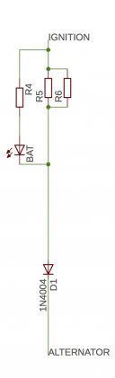
As I understand it, from discussions earlier in this thread, current flows directly to the alternator, via the two resistors R5 and R6, when the alternator isn't generating anything - this is to excite the alternator. It also flows through R4 and the LED in this state, so the LED lights up. But once the alternator is generating, wouldn't the ignition and the alternator be at the same potential, meaning nothing flows in any part of this circuit? I wonder if the LED I'm using is more sensitive (i.e. it lights with much lower current) than the original one - it's certainly brighter. But even so, it shouldn't matter how sensitive it is if there's no current flowing.
So what's causing the current flow through my new LED? I'm thinking it's something to do with that diode - does it hold the LED side a fraction above the alternator side, creating a little bit of current flow through the LED? Would a slightly higher resistance for R4 be enough to stop the LED glimmering if that's the case?
"I'm a man of means, by no means....King of the Road!"
1983 Viking Xplorer, 2.1DJ
1983 Viking Xplorer, 2.1DJ
Re: Replacing the dashboard plastic PCB
I've sorted out all the niggles that I'm aware of in this first prototype:
- Space cleared around the DOPS connector
- Oil pressure input labels corrected
- (coolant and fuel gauge labels already read '-ve' but were obscured by the terminals)
- All labels nudged away from the screw-down terminals so that they don't get obscured
- Dashlights pin headers nudged up a few mm so that the solder lugs clear the LED housing
- Power connector joined to the gauges connector for extra mechanical strength
- 'Spare' terminal and LED renamed as 'LED6'
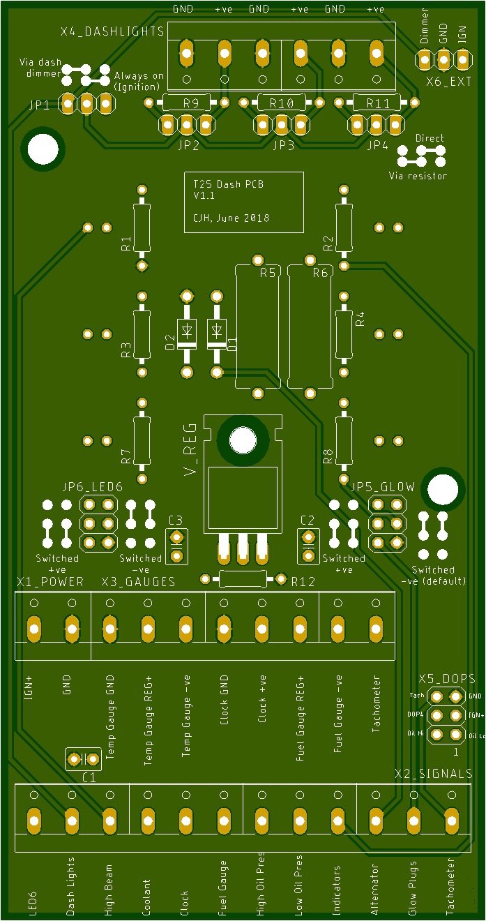
And finally I added an extra connector, 'X6_EXT', in the form of a simple pin header at the top right, so that I can easily connect the backlights for my external oil pressure and temperature gauges into the dashboard lighting. No resistor needed here because the gauge lighting is self-contained, but I did include the option to feed them from the dimmer or direct from the ignition live. Spotted that this morning when I fitted the dash to my van and had to double up in one of the dash lighting terminals, which aren't quite as accessible once the dash is back in the van - a 2-pin header will be much simpler to connect to.
Will aim to order these PDQ so that I have them for the weekend again.
- Space cleared around the DOPS connector
- Oil pressure input labels corrected
- (coolant and fuel gauge labels already read '-ve' but were obscured by the terminals)
- All labels nudged away from the screw-down terminals so that they don't get obscured
- Dashlights pin headers nudged up a few mm so that the solder lugs clear the LED housing
- Power connector joined to the gauges connector for extra mechanical strength
- 'Spare' terminal and LED renamed as 'LED6'
And finally I added an extra connector, 'X6_EXT', in the form of a simple pin header at the top right, so that I can easily connect the backlights for my external oil pressure and temperature gauges into the dashboard lighting. No resistor needed here because the gauge lighting is self-contained, but I did include the option to feed them from the dimmer or direct from the ignition live. Spotted that this morning when I fitted the dash to my van and had to double up in one of the dash lighting terminals, which aren't quite as accessible once the dash is back in the van - a 2-pin header will be much simpler to connect to.
Will aim to order these PDQ so that I have them for the weekend again.
"I'm a man of means, by no means....King of the Road!"
1983 Viking Xplorer, 2.1DJ
1983 Viking Xplorer, 2.1DJ
Re: Replacing the dashboard plastic PCB
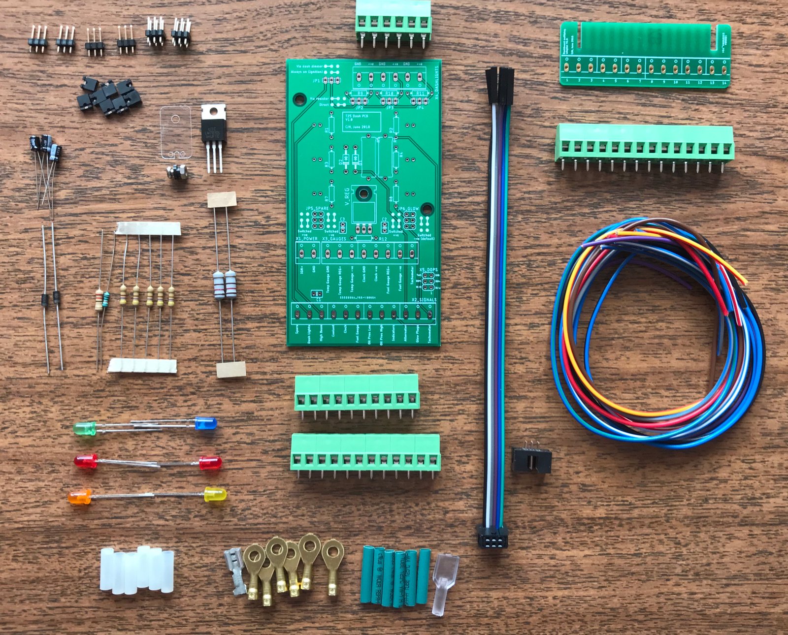
This morning I finished assembling this prototype board, to check for any other blunders before ordering the next iteration. I added a sixth LED so that I could test one as 'switched +ve' and one as 'switched -ve' **, and I added the three capacitors (and the one I mistakenly called the clock supply is of course the temperature gauge supply). And I added a little 2x3 pin header for the DOPS cable - can't really do any more than check for continuity as I don't have the DOPS system on my dash, but it passed the continuity check at least.
So I've been thinking about making up a kit for self-assembly. This shows most of what would be included. All that's missing really is the dash illumination bulbs. Not sure what to do here. The problem is that the original bulbs don't have leads - they make (a usually dodgy) contact with the original flexible circuit board. I haven't found a conveniently wired socket that fits the bulb holes snuggly without modification, so the options seem to be to modify the bulb holes and go with a different bulb holder, or to solder wires onto the original bulbs (which is what I did, but it's very easy to melt the bulb housing a bit in the process!). So I'm tempted to leave this aspect to the individual and not include anything in the kit, unless someone has a recommendation for a wired bulb holder that fits the dash.
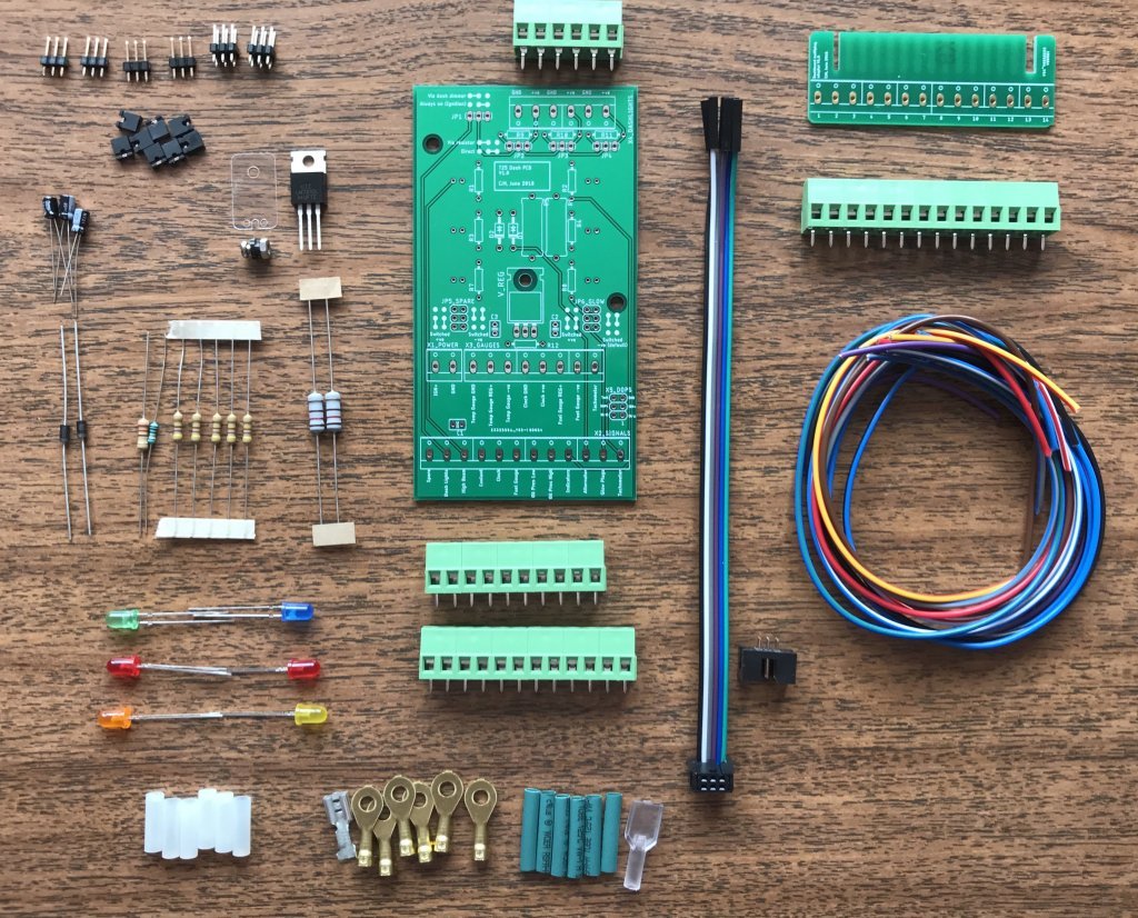
** I'm thinking one of the spare LEDs could be put to use as a towing indicator repeater. I have a buzzer, but it's in the engine bay, and not easy to hear.
So I've been thinking about making up a kit for self-assembly. This shows most of what would be included. All that's missing really is the dash illumination bulbs. Not sure what to do here. The problem is that the original bulbs don't have leads - they make (a usually dodgy) contact with the original flexible circuit board. I haven't found a conveniently wired socket that fits the bulb holes snuggly without modification, so the options seem to be to modify the bulb holes and go with a different bulb holder, or to solder wires onto the original bulbs (which is what I did, but it's very easy to melt the bulb housing a bit in the process!). So I'm tempted to leave this aspect to the individual and not include anything in the kit, unless someone has a recommendation for a wired bulb holder that fits the dash.
** I'm thinking one of the spare LEDs could be put to use as a towing indicator repeater. I have a buzzer, but it's in the engine bay, and not easy to hear.
"I'm a man of means, by no means....King of the Road!"
1983 Viking Xplorer, 2.1DJ
1983 Viking Xplorer, 2.1DJ