I'm wanting to add some circuits to my relatively basic van (headlight relays, twin tone horn, timed interior light relay etc) and would rather use some of the vacant spaces on the box rather than find space and make brackets behind the dash which would be a pain if yhe relay fails.
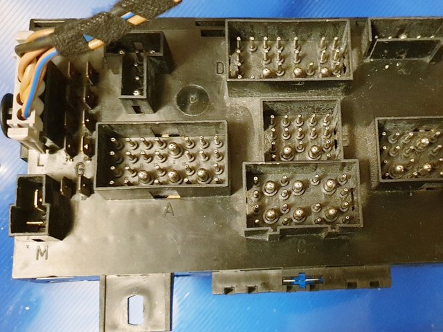
As such I'm not so much looking for a diagram that tells me which relay/fuse slot does what but more so hoe the front terminals and rear terminals are connected internally. Is anything like this available before I split my fusebix?
Sent from my SM-G960F using Tapatalk
Late Fuse Box Internal Wiring Diagram
Moderators: User administrators, Moderators
-
Mocki

- Membership Admin
- Posts: 16977
- Joined: 29 Sep 2005, 09:27
- 80-90 Mem No: 428
- Location: Mansfield Notts
- Contact:
Re: Late Fuse Box Internal Wiring Diagram
You need to search for "central electrics"
fusebox ce1
http://www.a2resource.com/electrical/CE1.html
fusebox ce1
http://www.a2resource.com/electrical/CE1.html
Steve
tel / txt O7947-137911

________________
1989 2.1LpgWBX HiTop Leisuredrive Camper
1988 2.1 Caravelle TS TinTop Camper
tel / txt O7947-137911

________________
1989 2.1LpgWBX HiTop Leisuredrive Camper
1988 2.1 Caravelle TS TinTop Camper
-
Robsey

- Registered user
- Posts: 1171
- Joined: 19 May 2012, 20:45
- 80-90 Mem No: 11137
- Location: East Manchester
Re: Late Fuse Box Internal Wiring Diagram
I did a map of relays and their associated pins.
I am doing an upgrade from a 1983 torpedo fusebox to a 1987 CE1 fusebox with upgraded horns and headlamps.
The dual tone horns is easy, because they already have a designated relay - No 6, type 53. (General function relay).
The tricky bit is getting a "L" connector.
They have long since stopped selling them.
For the headlamps, I fitted two externally mounted relays on the top of the CE1 box next to the link fuses
Again - general type 53 relays - one for high beam and one for dipped beam.

Here is my fusebox listing thread.
viewtopic.php?f=39&t=173773&start=15
I am doing an upgrade from a 1983 torpedo fusebox to a 1987 CE1 fusebox with upgraded horns and headlamps.
The dual tone horns is easy, because they already have a designated relay - No 6, type 53. (General function relay).
The tricky bit is getting a "L" connector.
They have long since stopped selling them.
For the headlamps, I fitted two externally mounted relays on the top of the CE1 box next to the link fuses
Again - general type 53 relays - one for high beam and one for dipped beam.
Here is my fusebox listing thread.
viewtopic.php?f=39&t=173773&start=15
1983 Tin Top with a poorly DF and 4 speed DT box.
1987 Electrics and a DJ engine.
Maybe one day I might get it finished
1987 Electrics and a DJ engine.
Maybe one day I might get it finished
-
TONYT25T25
- Registered user
- Posts: 1828
- Joined: 16 Sep 2013, 17:19
- 80-90 Mem No: 13596
- Location: Hampshire
Re: Late Fuse Box Internal Wiring Diagram
Talking about torpedo fuses, is there a special tool for removing and replacing them, my sausage fingers have a job doing it.
1984 Campervan 1.9DG Petrol WBX
-
Stesaw
- Registered user
- Posts: 1911
- Joined: 10 Aug 2019, 23:30
- 80-90 Mem No: 17004
- Location: Coventry
Re: Late Fuse Box Internal Wiring Diagram
With the torpedo ones If I recall you just push down a bit and you should be able to lift them out.
1985 LeisureDrive 2.1DJ 5 Speed syncro conversion project.
1979 LT 2.0CH Westy project
1979 LT 2.0CH Westy project
-
syncroandy

- Trader
- Posts: 1857
- Joined: 18 Oct 2005, 18:15
- 80-90 Mem No: 851
- Location: North Lancs. UK
- Contact:
Re: Late Fuse Box Internal Wiring Diagram
The connections inside the relay plate are shown in the grey section at the top of each page in the wiring diagrams.
oli8925 wrote: ↑18 Sep 2021, 12:43 I'm wanting to add some circuits to my relatively basic van (headlight relays, twin tone horn, timed interior light relay etc) and would rather use some of the vacant spaces on the box rather than find space and make brackets behind the dash which would be a pain if yhe relay fails.
As such I'm not so much looking for a diagram that tells me which relay/fuse slot does what but more so hoe the front terminals and rear terminals are connected internally. Is anything like this available before I split my fusebix?
Sent from my SM-G960F using Tapatalk
Syncrosport
Volkswagen Transporter, reloaded.
252 GC5 EJ25 AAN L90D
246 097 AFN AVL+ L90D
Syncronaut #004
Volkswagen Transporter, reloaded.
252 GC5 EJ25 AAN L90D
246 097 AFN AVL+ L90D
Syncronaut #004
-
TONYT25T25
- Registered user
- Posts: 1828
- Joined: 16 Sep 2013, 17:19
- 80-90 Mem No: 13596
- Location: Hampshire
Re: Late Fuse Box Internal Wiring Diagram
Got you, makes sense, I normally just pull at them but now understand that pushing down probably opens up the contacts allowing easier removal. DOH as Homer says.
1984 Campervan 1.9DG Petrol WBX
-
Stesaw
- Registered user
- Posts: 1911
- Joined: 10 Aug 2019, 23:30
- 80-90 Mem No: 17004
- Location: Coventry
Re: Late Fuse Box Internal Wiring Diagram
TONYT25T25 wrote: ↑18 Sep 2021, 21:18
Got you, makes sense, I normally just pull at them but now understand that pushing down probably opens up the contacts allowing easier removal. DOH as Homer says.. Although putting new ones in is sometimes a bit of a faff due to close proximity of other fuses.
Same procedure in reverse
1985 LeisureDrive 2.1DJ 5 Speed syncro conversion project.
1979 LT 2.0CH Westy project
1979 LT 2.0CH Westy project
-
Robsey
- Registered user
- Posts: 1171
- Joined: 19 May 2012, 20:45
- 80-90 Mem No: 11137
- Location: East Manchester
Re: Late Fuse Box Internal Wiring Diagram
As people like tables...
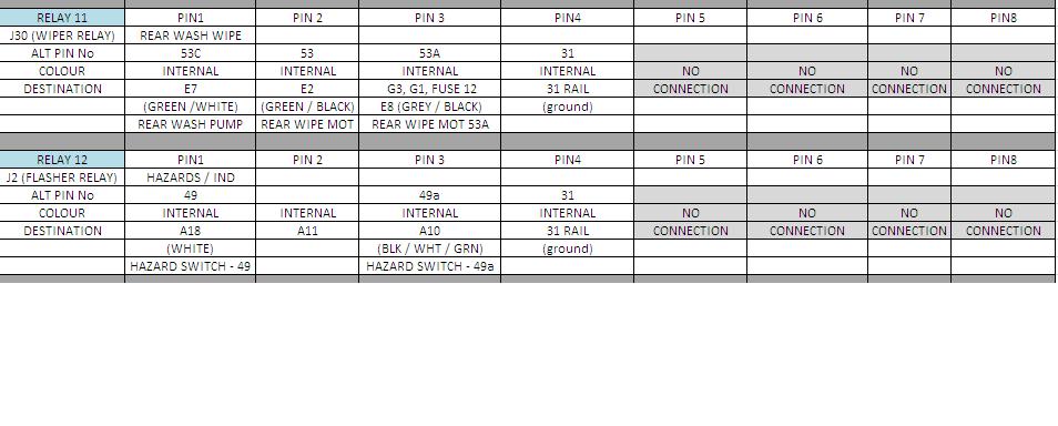
Here is the pin outs for the relays.
Note that relay 9 is actually just a fuse socket or may be blanked off completely.
So here are the tables.
Relays 1 to 5

Relays 6 to 10
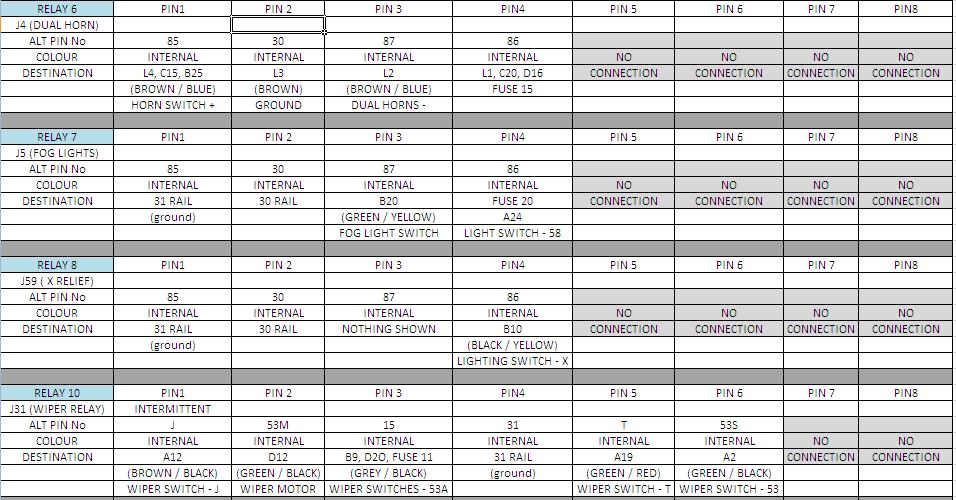
Relays 11 and 12.
As said earlier, I wired my head-lamps to clip / slide on relay sockets on the top of the fuse box.
That is why I put the ladder diagram there for the lights.
Also for info Alt Pin means alternative pin number... not alternator.
And I am sure you know what the "rail" number means..
But just in case -
Rail 15 - ignition live
Rail 30 - battery live
Rail 31 - ground / chassis / earth.
Rail 50 - starter cranking wire
Rail 61 - alternator charge light
Rail X - voltage when engine is running (relief relay output).
Here is the pin outs for the relays.
Note that relay 9 is actually just a fuse socket or may be blanked off completely.
So here are the tables.
Relays 1 to 5
Relays 6 to 10
Relays 11 and 12.
As said earlier, I wired my head-lamps to clip / slide on relay sockets on the top of the fuse box.
That is why I put the ladder diagram there for the lights.
Also for info Alt Pin means alternative pin number... not alternator.
And I am sure you know what the "rail" number means..
But just in case -
Rail 15 - ignition live
Rail 30 - battery live
Rail 31 - ground / chassis / earth.
Rail 50 - starter cranking wire
Rail 61 - alternator charge light
Rail X - voltage when engine is running (relief relay output).
Last edited by Robsey on 20 Sep 2021, 22:46, edited 6 times in total.
1983 Tin Top with a poorly DF and 4 speed DT box.
1987 Electrics and a DJ engine.
Maybe one day I might get it finished
1987 Electrics and a DJ engine.
Maybe one day I might get it finished
-
Robsey
- Registered user
- Posts: 1171
- Joined: 19 May 2012, 20:45
- 80-90 Mem No: 11137
- Location: East Manchester
Re: Late Fuse Box Internal Wiring Diagram
I am sure it is Wiki'd somewhere but to keep all info in one place..
Relay 1 - not used.
Relay 2 - not used
Relay 3 - Coolant shortage indicator - type 42 or 43
Relay 4 - not used
Relay 5 - 2nd Stage rad fan (air con vans) - type 53
Relay 6 - Dual tone horns / fanfare - type 53
Relay 7 - Fog lights - type 53
Relay 8 - X relief relay - type 18 or 100
Relay 9 - fuse socket / or blanked off.
Relay 10 - Intermittent wiper relay - type 19 or 99
Relay 11 - Rear wash wipe relay - type 72
Relay 12 - Flasher relay - type 21 or 22
Last edited by Robsey on 19 Sep 2021, 12:09, edited 2 times in total.
1983 Tin Top with a poorly DF and 4 speed DT box.
1987 Electrics and a DJ engine.
Maybe one day I might get it finished
1987 Electrics and a DJ engine.
Maybe one day I might get it finished
-
Robsey
- Registered user
- Posts: 1171
- Joined: 19 May 2012, 20:45
- 80-90 Mem No: 11137
- Location: East Manchester
Re: Late Fuse Box Internal Wiring Diagram
As an added quirk,
I used the 2nd stage fan relay to allow a dash mouted "overide" switch for the radiator cooling fan.
Probably un-necessary, but I just like the idea of a back up plan so that I can have the fan running if I feel there is a potential over heating issue - such as an arduous route or a very hot day.
I used the 2nd stage fan relay to allow a dash mouted "overide" switch for the radiator cooling fan.
Probably un-necessary, but I just like the idea of a back up plan so that I can have the fan running if I feel there is a potential over heating issue - such as an arduous route or a very hot day.
1983 Tin Top with a poorly DF and 4 speed DT box.
1987 Electrics and a DJ engine.
Maybe one day I might get it finished
1987 Electrics and a DJ engine.
Maybe one day I might get it finished
-
Stesaw
- Registered user
- Posts: 1911
- Joined: 10 Aug 2019, 23:30
- 80-90 Mem No: 17004
- Location: Coventry
Re: Late Fuse Box Internal Wiring Diagram
Sounds smart, I've thought about a "chicken switch" but as the system is all working it should it kicks in when it needs to.
1985 LeisureDrive 2.1DJ 5 Speed syncro conversion project.
1979 LT 2.0CH Westy project
1979 LT 2.0CH Westy project
-
Robsey
- Registered user
- Posts: 1171
- Joined: 19 May 2012, 20:45
- 80-90 Mem No: 11137
- Location: East Manchester
Re: Late Fuse Box Internal Wiring Diagram
Here is my headlamp wiring.
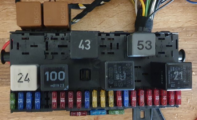
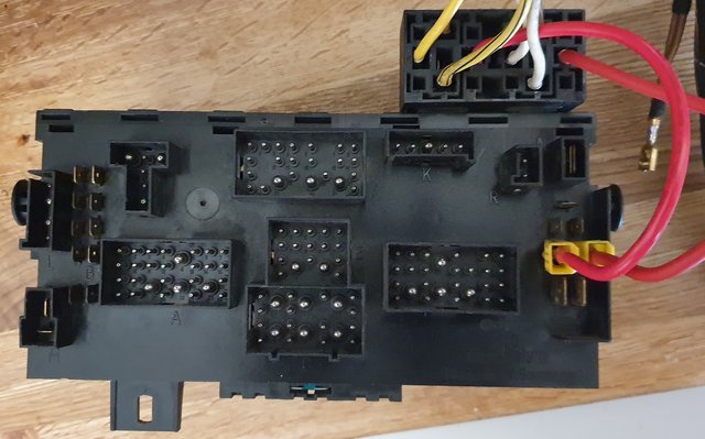
Very simple really.
The diagram is wrong though.
It mentions S21 (fuse 21).
That is not the supply wire.
Battery live is from two of the 'P' spade connectors.
Output from the relays do go to the relevant fuses via pins A21 and B22
The input trigger wires to the relays are the wires that WERE originally in those pin positions to reduce the current going through the light switch and high/low beam stalk switch.
Ground wires can go any where.
You can see brown Bosch relays in my supplementary locations. These are general purpose relays left over from various Vauxhall projects.
They are suitably rated and do exactly the same job as the VW 53 relay.
I also have an early 24 relay fitted in the picture that is supposed to do the same job as a 53
Last edited by Robsey on 30 Oct 2021, 17:42, edited 3 times in total.
1983 Tin Top with a poorly DF and 4 speed DT box.
1987 Electrics and a DJ engine.
Maybe one day I might get it finished
1987 Electrics and a DJ engine.
Maybe one day I might get it finished
-
Robsey
- Registered user
- Posts: 1171
- Joined: 19 May 2012, 20:45
- 80-90 Mem No: 11137
- Location: East Manchester
Re: Late Fuse Box Internal Wiring Diagram
As for the chicken switch - it works great on cars where the engine is directly behind the fan - such as anything front wheel drive.
Running the fan in a standard car means that I have been able to 'limp' home safely with the fan running despite a burst radiator. And each time, I have not cooked the engine.
In those instances I simply bridged the contacts of the rad fan connector with a blade fuse.
But - because the fan is some 14 foot or more away from the engine, it would not work with a coolant leak, but it may help just to keep the cooling system cooler for longer when they are at most demand.
In my situation, I have the CE1 loom for a DJ with pas and air-con, but my van has neither power steering nor air-con, so for the sake of a couple of wires and a switch (I used a heated rear window switch - my van doesn't have that either) . it is a cheap and easy addition.
Better to have and not need, than..... you know the rest.
Just for info - check carefully what model year wiring diagrams you have.
There are significant differences between the 1989 and 1990 diagrams.
Such as parking lights, head lamp switch, dim/dip lighting, dual tone horns and so much more.
Running the fan in a standard car means that I have been able to 'limp' home safely with the fan running despite a burst radiator. And each time, I have not cooked the engine.
In those instances I simply bridged the contacts of the rad fan connector with a blade fuse.
But - because the fan is some 14 foot or more away from the engine, it would not work with a coolant leak, but it may help just to keep the cooling system cooler for longer when they are at most demand.
In my situation, I have the CE1 loom for a DJ with pas and air-con, but my van has neither power steering nor air-con, so for the sake of a couple of wires and a switch (I used a heated rear window switch - my van doesn't have that either)
Better to have and not need, than..... you know the rest.
Just for info - check carefully what model year wiring diagrams you have.
There are significant differences between the 1989 and 1990 diagrams.
Such as parking lights, head lamp switch, dim/dip lighting, dual tone horns and so much more.
Last edited by Robsey on 19 Sep 2021, 16:58, edited 1 time in total.
1983 Tin Top with a poorly DF and 4 speed DT box.
1987 Electrics and a DJ engine.
Maybe one day I might get it finished
1987 Electrics and a DJ engine.
Maybe one day I might get it finished
-
Robsey
- Registered user
- Posts: 1171
- Joined: 19 May 2012, 20:45
- 80-90 Mem No: 11137
- Location: East Manchester
Re: Late Fuse Box Internal Wiring Diagram
For single horn to dual tone / fanfare conversion.
Single horn version
Fuse 16 (15 amps) supplies pin C13 (internal)
Pin C13 goes to Horn + (black/ yellow 1.0mm)
Horn - goes to pin C15 (brown/blue 1.0mm).
Pin B25 - goes to horn switch + (brown/blue 1.0mm).
Horn Switch - to ground via links through steering column.
Dual Horn Version.
Fuse 16 (15 amps) supplies pin C13 (internal)
Pin C13 goes to Horn + (black/ yellow 1.0mm)
(I fitted two parallel wires 1.0mm each or you could fit one wire at 1.5mm csa).
Horn - goes to "L" connector pin L2 (brown/blue 1.5mm)
Pin L4 - goes to pin C15 (brown/blue 0.5mm)
Pin B25 - goes to horn switch + (brown/blue 1.0mm).
Horn Switch - to ground via links through steering column.
Wires to add for relay
Fuse 15 (10 amps) goes to pin L1 (internal).
Pin L1 goes to pin C20 (black 0.5mm)
Pin L3 goes to ground (brown 1.5mm).
That is it.
Last edited by Robsey on 23 Sep 2021, 07:40, edited 1 time in total.
1983 Tin Top with a poorly DF and 4 speed DT box.
1987 Electrics and a DJ engine.
Maybe one day I might get it finished
1987 Electrics and a DJ engine.
Maybe one day I might get it finished