VNT Turbo - the inside info

for questions and answers about alternative power transplants on the T25, GTi, Porsche,Subaru etc, this is the place. You must register to post but anyone can read.

Moderators: User administrators, Moderators

Post Reply
futbus
Trader
Posts: 498
Joined: 18 Oct 2005, 16:25
80-90 Mem No: 1266
Location: South Devon
Contact:

VNT Turbo - the inside info

Post by futbus »

We bought some turbos all off cars of less than 5 years old and main dealer returns, but all had issues mainly stuck vanes or damage to the vanes.

The stripdown is fairly straight forward so no point documenting this. Turbo stripped was a good 2011 unit although a fair bit of carbon build up and was sticking. After stripping the unit went into an ultrasonic cleaner to get the most off.

So the main parts of a turbo are divided into 3 parts

Image

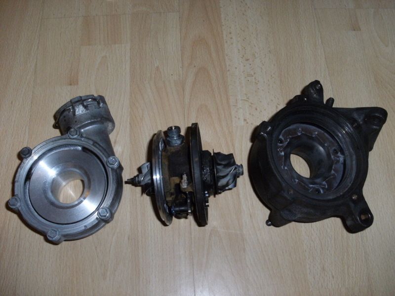
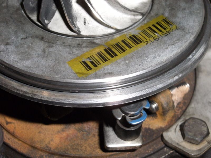
The main impeller shaft
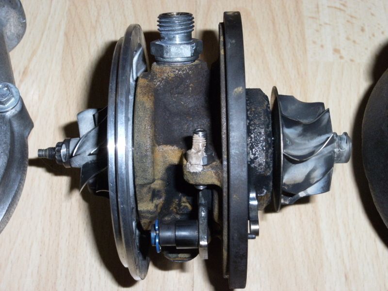
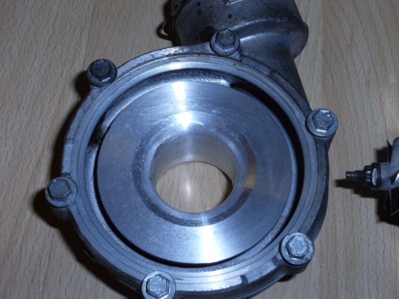
Image

Fresh air side

Image

Exhaust side

Image

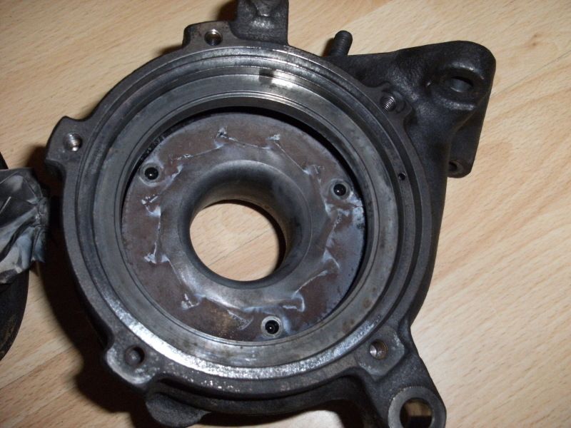
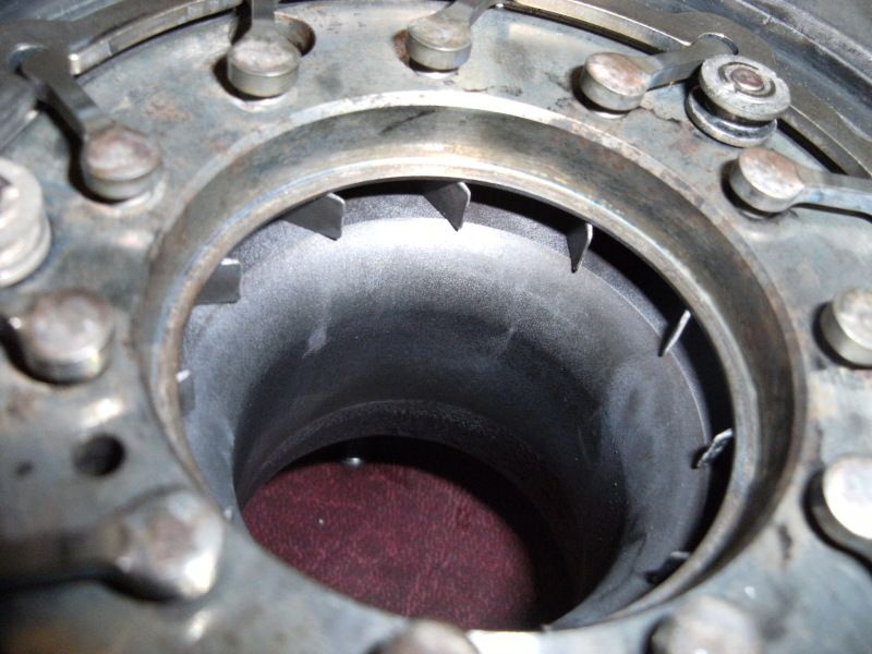
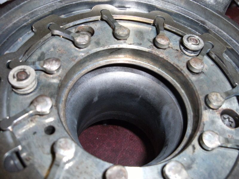
The vnt has variable vanes

Image

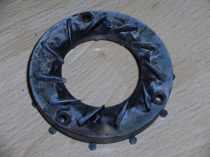
These are controlled by a cam arrangement

Image

These move and control the exhaust gases through the turbo changing the speed of the vane shaft

Image

Image

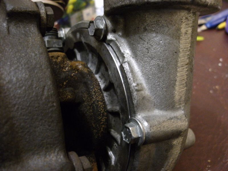
This is installed into the exhaust side of the turbo

Image

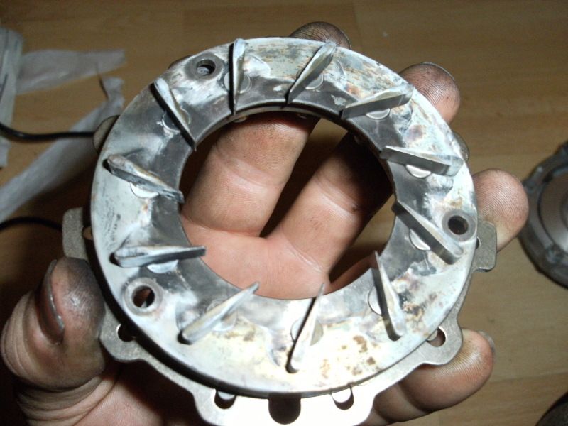
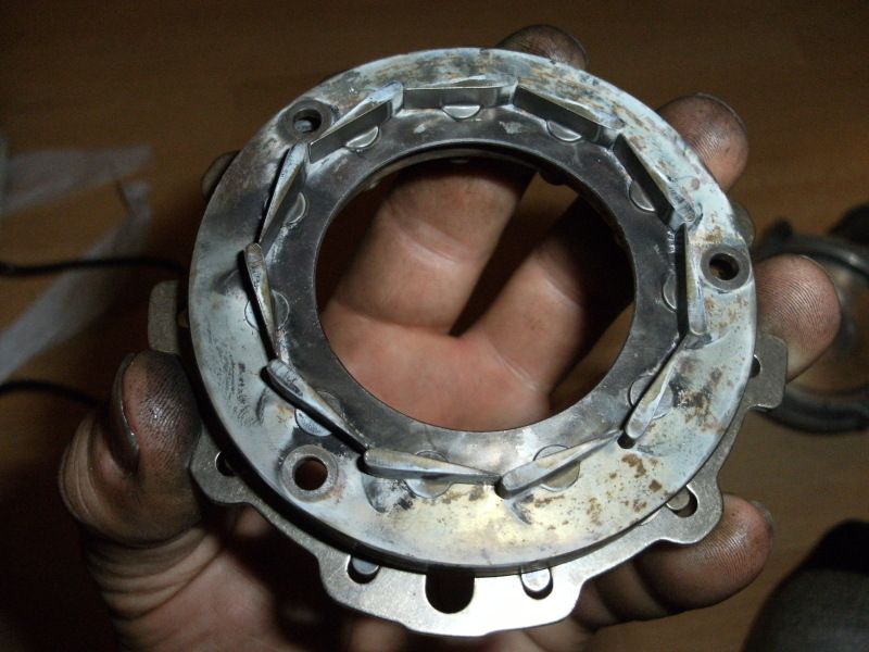
Closer look at what the adjustable vanes look like in the main exhaust side in each position

Image

Image

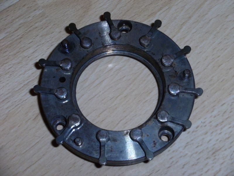
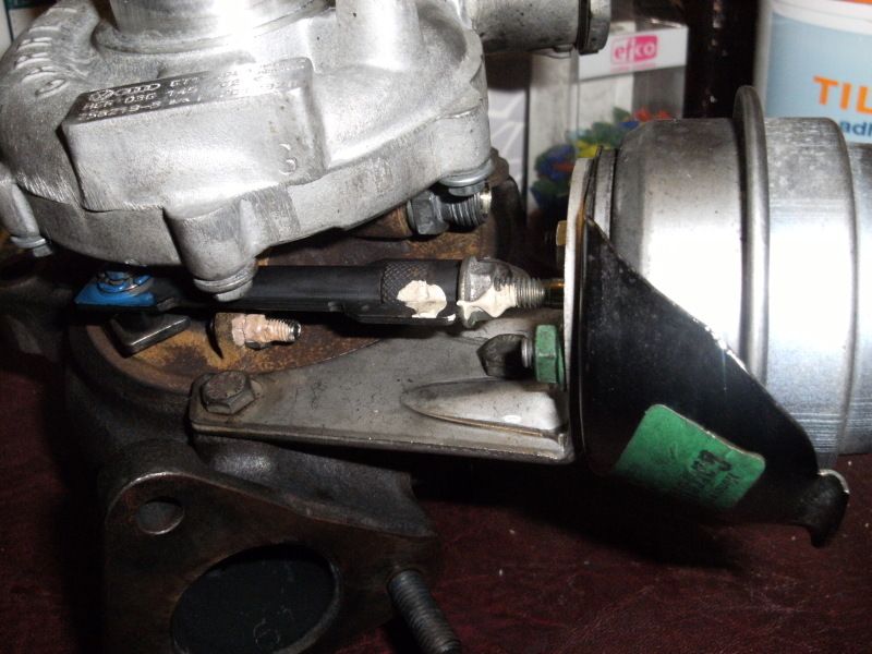
The control of the adjuster is via a cam through the body to the outside and connected to diaphram control

Image

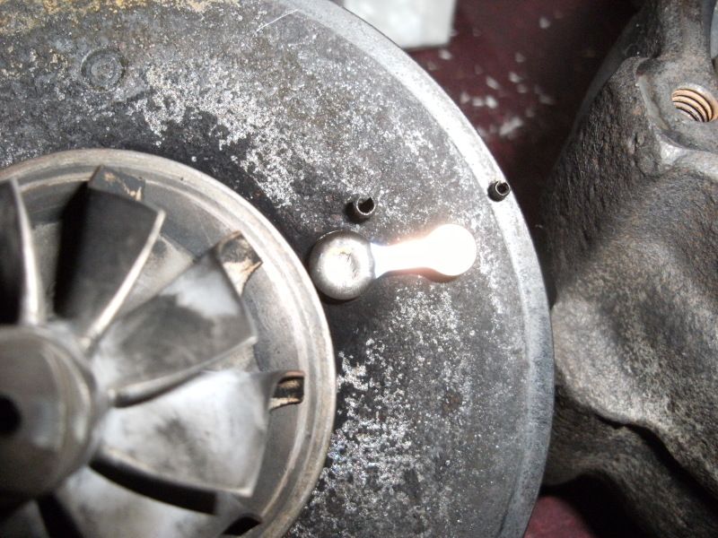
control for the vanes as seen from the outside of the exhaust side of turbo

Image

New `O` ring installed onto the fresh air side of turbo housing

Image

Fresh air housing installed back on

Image

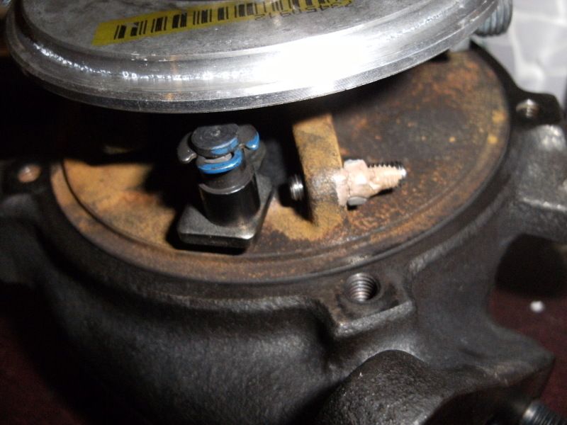
Diaphram control for the turbo vanes installed

Image

Full turbo now back together and working

Image

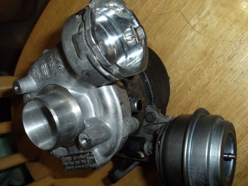
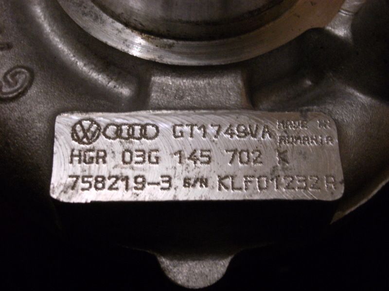
Details of the casting number of the turbo thats been rebuilt

Image

If anyone has details that they can add to this thread then feel free to share info.

User avatar
..lee..
Registered user
Posts: 733
Joined: 04 Jun 2006, 22:13
80-90 Mem No: 4478
Location: llanelli, s wales

Re: VNT Turbo - the inside info

Post by ..lee.. »

be carefull fitting the vnt17 and bigger nozzles. i wasn`t :lol:
it`s a big round cage and there`s too many animals in it for my liking. To help address this ring lee on 07977 765818.

User avatar
syncroandy
Trader
Posts: 1857
Joined: 18 Oct 2005, 18:15
80-90 Mem No: 851
Location: North Lancs. UK
Contact:

Re: VNT Turbo - the inside info

Post by syncroandy »

I also R&R'd the VNT15 I used on my AFN build, well worth doing. One thing I'd didn't do was to use a vacuum gauge to adjust the start of actuation of the diaphragm, as I didn't have a suitable gauge. I just set it back to how it was when I took it apart. It had an AR of .33 though most seem to be .46, seems to work just fine though, I get .5bar 'normal' boost, going up to around 1.2bar under heavy load.

There do seem to be quite a few different part numbers for the VNT15 depending on the vehicle. I suspect the actuator and oil inlet/outlets positions may vary, but as I've not had them through my hands I don't know for sure. I expect some variants lend themselves to use (with an adapter) on the JX manifold more than others. It'd be good to hear of combinations that are proven to work. All I can say is the 3b Passat turbo/mani do work, I used a stock VW oil feed and custom return.

Agree with Lee, IMO any non-standard turbo, nozzles etc. should be accompanied with a suitable re-map otherwise running characteristics of the engine will deviate from those designed, with possible unfortunate consequences..
Syncrosport
Volkswagen Transporter, reloaded.

252 GC5 EJ25 AAN L90D
246 097 AFN AVL+ L90D
Syncronaut #004

Post Reply